Resistive Electrodes
How can a voltage gradient be defined on an electrode in SIMION (such as due to a resistive material)?
This is possible in SIMION, but it requires a few tricks to input the geometry.
Why voltage gradients on electrodes? Voltage gradients on electrodes (e.g. resistive materials) can be useful in ion mobility tubes (e.g. Photonis resistive glass), reflectrons, and cycloidal mass specs in order to generate a linearly increasing potential (constant electric field) over space. Sometimes, a series of conductive electrodes at increasing potential are used instead of resistive material, but this is more complicated and is only an approximation.
There are multiple methods of applying a voltage gradient on electrodes:
Method 0: GEM files
Method 1: A trick using Refine
Method 2: Programmatically modifying the PA file
Method 3: Dielectric solver
Method 0: GEM Files
As of SIMION 8.2EA20170328, in GEM files,
the electrode command (gem e())
can accept a function defining a gradient:
; sphere with gradient voltage over surface
pa_define {21,21,21}
local function f(x,y,z)
  return x+y
end
e(f) { sphere(10,10,10, 10) }
Another example:
-- circular electrode with linear gradient potential
pa_define {30,30,1, symmetry='planar[xy]'}
local function linear(x1,v1, x2,v2)
  return function(x,y,z)
    local f = (x - x1) / (x2 - x1)
    return (1 - f) * v1 + f * v2
  end
end
e(linear(5,100, 10,200)) {
  circle(0,0, 20)
}
Method 1: A trick using Refine
This trick works only in cases where the system can be altered to omit electrodes in such a way that the Refine process will calculate the desired potentials at the omitted electrodes. After refining, the points on the omitted electrodes can be changes from non-electrode points to electrode points while preserving the potentials (e.g. using the Find/Replace function in Modify).
The reflecton (TOF/MIRROR.PA) example in SIMION 7.0 was created using this method.
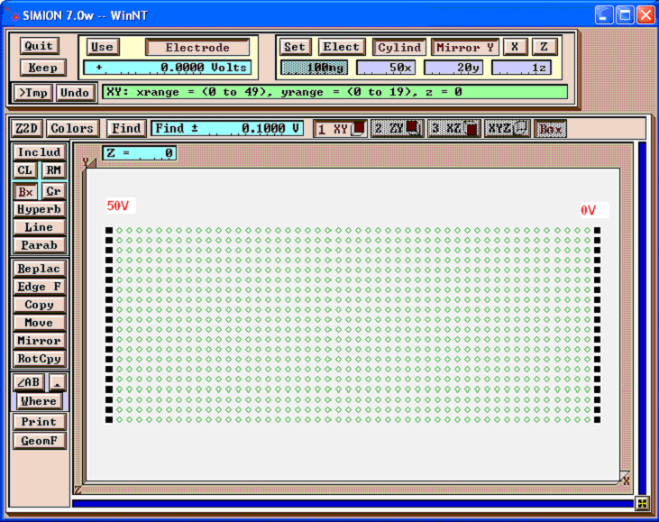
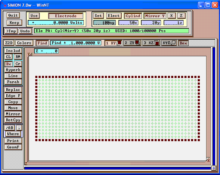
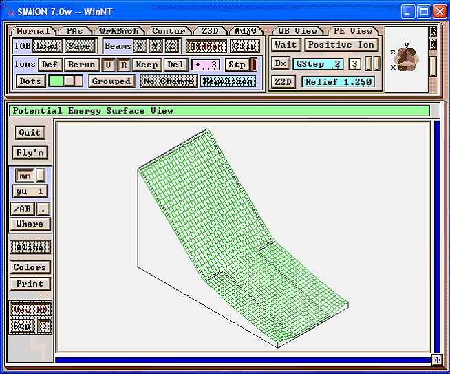
Example: First, draw two electrodes as shown (we omit the electrodes at the top and bottom, which will have a voltage gradient):
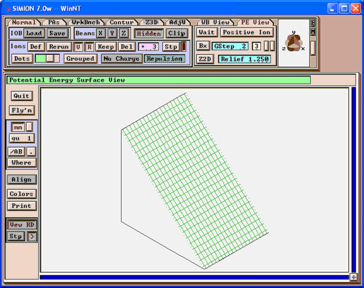
Refine this. The potential energy map of the result is shown below:

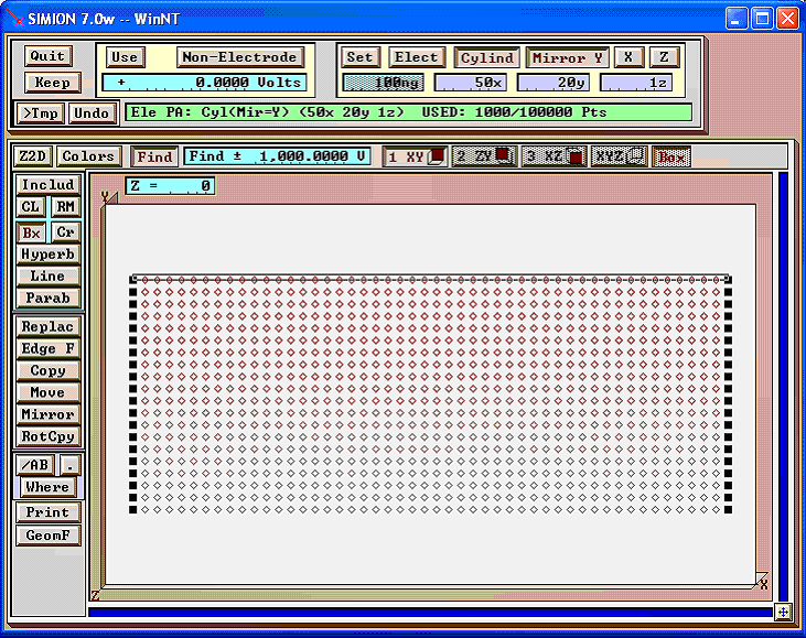
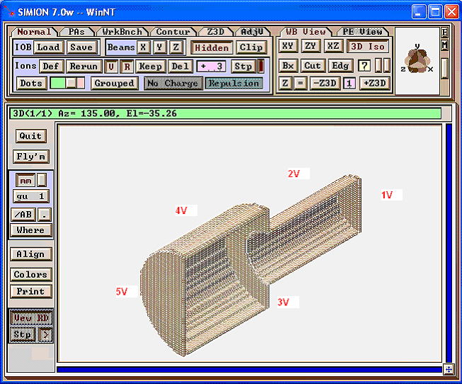
Now, open this refined PA in Modify. You will see that the potentials at the non-electrode points have been calculated. Let�s change some of these points into electrode points.
First, select the points you want to change to electrodes, and enable “Non-Electrode”, “0 Volts”, “Find”, and “Find +- 1000 V” (some large value). This finds all non-electrode points of voltages 0 +- 1000 V.
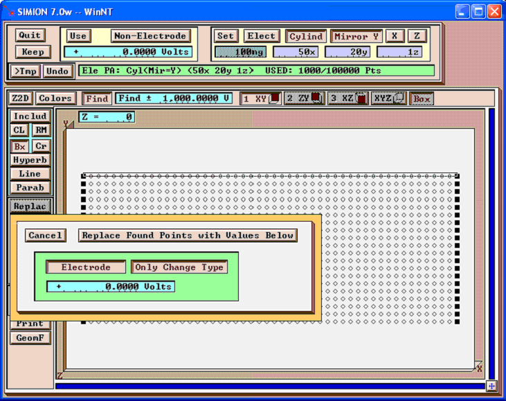
Next, click “Replace”, and enable “Electrode” and “Only Change Type” to change these points to electrode points (without altering the potentials).
Below is the result:
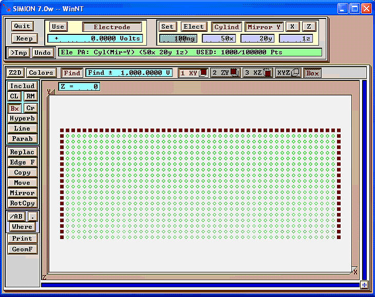
Do the same for the bottom electrode as well:
You may wish to re-refine at this point (in this case, it should not make any difference). Below is the potential energy map of the result:
Method 2: Programmatically modifying the PA file
This method is the more general method and will work in all cases via some code. See the SIMION Example: resistive added in SIMION 8.1.1.18. This supports both PA and PA# files.
The pa:flood_fill (added in
SIMION 8.2) may be even easier:
local pa = simion.pas[1]
pa:flood_fill(0,0,0, function(x,y,z)
  pa:potential(x,y,z, x*10)  -- apply voltage gradient to electrode
end)
Below is an older example using SL Libraries to programmatically edit the PA file (outside of SIMION), which works in SIMION 8.0 or above.
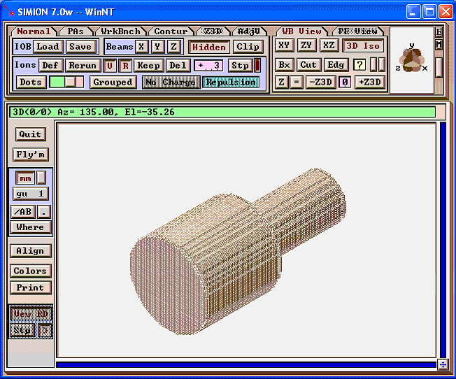
Example: First, create a potential array without voltage gradients on electrodes:
Now, run the below apply_resistance.py Python program (which uses
the SIMION SL Toolkit’s SL Libraries for Python), which reads in
mod_in.pa and writes out mod.pa. This program modifies the
potentials on the electrodes. (Note: You’ll need to tell Python
where to find the SL Libraries, e.g. via the PYTHONPATH environment
variable.)
# apply_resistance.py
# Python program that modifies SIMION PA file to apply
# resistive material effects (e.g. voltage gradients
# along electrodes)
#
# Reads in mob_in.pa as input and writes out mob.pa as output.
#
# This requires the SIMION SL Toolkit (SL Libraries for Python).
# Tested with version 1.2.
#
# David Manura, Adaptas Solutions, LLC 2005-06-17

from SIMION.PA import *

# linear interpolation
#  given fixed points (x1, v1) and (x2, v2), find another point
#  (x, v) on the line, where x is given as well.
def interp(x1, v1, x2, v2, x):
    m = (v2 - v1) / (x2 - x1 + 0.0)
    v = v1 + m*(x - x1)
    return v

# load the input PA
pa = PA(file = 'mob_in.pa')

print pa.header_string()  # print some debug info

# iterative over all the points, changing the potentials
#   so as to simulate resistive material effects.
for z in range(0, pa.nz()):
    for y in range(0, pa.ny()):
        for x in range(0, pa.nx()):
            pot = pa.potential(x, y, z)
            #print pot
            if pot == 1 or pot == 2 or pot == 3:
                new_pot = interp(0, 10, 53, 20, z)
            elif pot == 4 or pot == 5:
                new_pot = interp(53, 20, 100, 50, z)
            else:
                new_pot = pot
            pa.potential(x, y, z, new_pot)

pa.save('mob.pa')

print "done"
Then refine the mod.pa in SIMION. The final results are shown below.
(There are also ways to do a similar thing in C++, Perl, or Lua code. See the latest swirl example (simion8-field-pa2text-swirl example from the “Check for Updates” button on the SIMION 8.0 main screen for background.)
Method 3: Dielectric solver
Resistive materials and/or dielectric materials can be treated with the dielectric support in SIMION 8.1 Refine. Here, dielectric constants or conductivities are specified over certain material regions. See Dielectrics and Current Density. Methods #1 and #2 above assume that you know the profile of potential over the entire resistive surface. This method does not make that assumption.
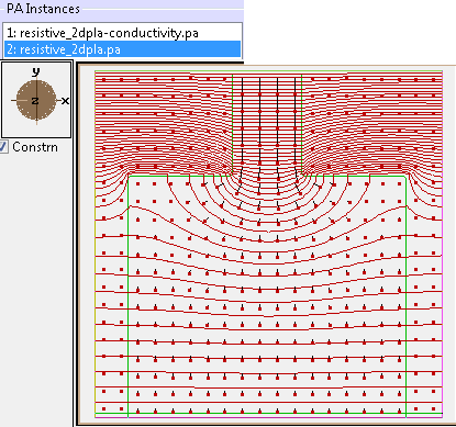
Fig. 59 Figure: This is from SIMION Example: dielectric (resistive_2dp.iob) in SIMION 8.1.1. Potential contour lines (red) and current density vectors (black lines with dots). The boundary between low (outside) and high (inside) conductivity regions is outlined in green (0.5 contour line). The magnitude of current density decreases as the conductor width widens at the bottom since current flux is conserved.