Engineering Tolerance
There can be ways to estimate acceptable engineering tolerances in SIMION. Generally, this can involve slightly perturbing some parameter and observing how this how this causes the final results to deviate in order to establish acceptable bounds for that parameter.
Mechanical tolerances affect how critical electrodes need to be when machined and positioned, which affects time, cost and stability [1][Wannberg1985]. For mechanical tolerancing, you might vary electrode position and examine to what degree this affects the particle trajectories. SIMION Example: geometry_optimization (in SIMION 8.0 and improved in 8.1) might also help automate this. Electrode Surface Enhancement / Fractional Grid Units may also be useful here if perturbed positions or angles are less than a grid unit (note: SIMION Example: surface_enhancement tilted_plates.iob is an example of angular tilt).
Other examples include perturbing electrode voltage and beam starting size/position/energy, which are very easy to check.
Off-Axis Misalignments in 2D Cylindrical Symmetry
For a 2D cylindrical PA, any off-axis misalignment will break 2D cylindrical symmetry, technically necessitating a 3D array with much more memory and calculation time. However, you may be able to obtain your answer without a 3D array.
If you’re just looking for order of magnitude estimation of effects of electrode misalignments, maybe simulate this 2D cylindrical system in 2D planar symmetry and evaluate the effect of Y misaligments in that 2D planar system.
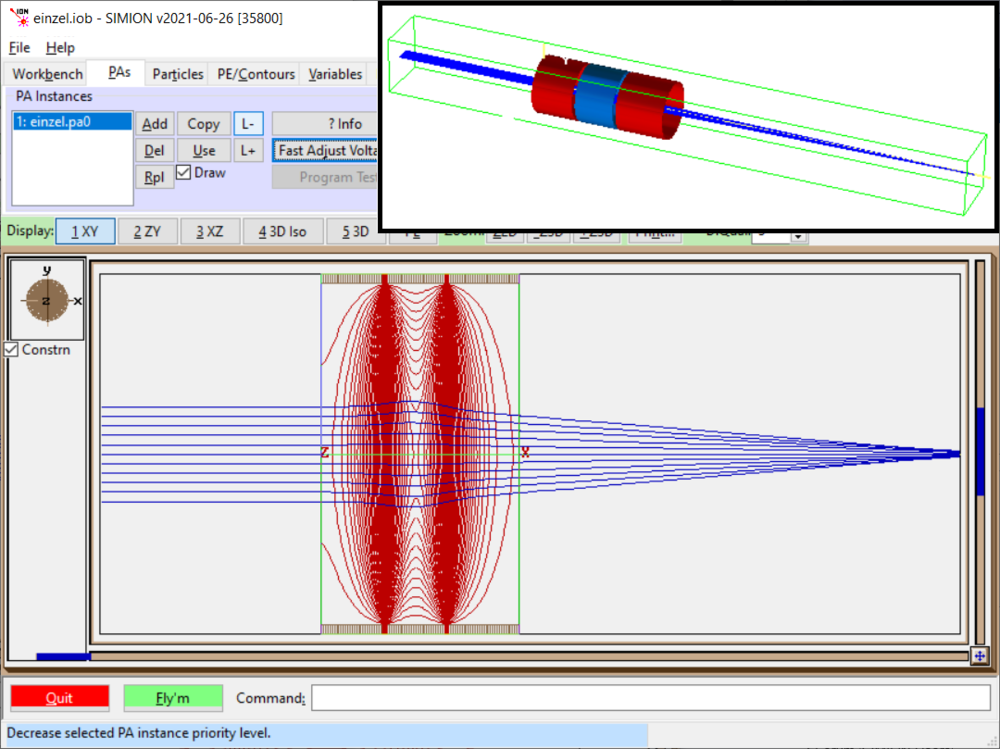
For example, the SIMION Example: einzel (einzel.iob) in SIMION, which uses 2D cylindrical symmetry, looks like this:
If we change the symmetry on the PA to 2D planar (keeping Y mirroring) and Re-refine, we get this:
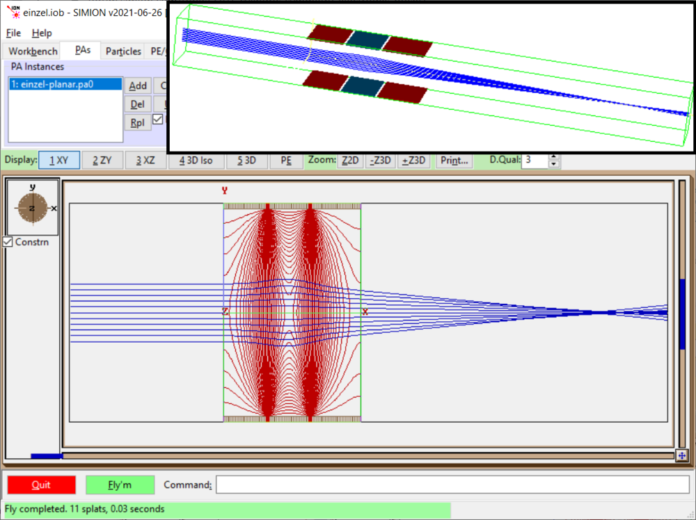
The result is different (shifted focus point and potential contour lines) but not terribly different qualitatively and quantitatively.
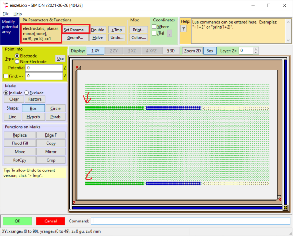
What we care about is how misalignments in electrodes affect the result, which we can evaluate in this 2D planar system. To allow that, let’s further covert this 2D planar PA with Y mirroring to 2D planar without Y mirroring and some extra space at the top to allow shifting electrodes in Y:
We didn’t change anything fundamentally, so the 2D planar system result remains the same:
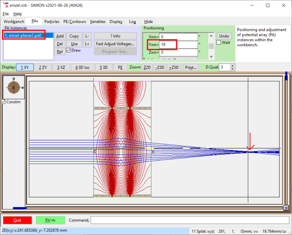
Now, let’s Y shift the center electrode (e.g. 3 grid units used here):
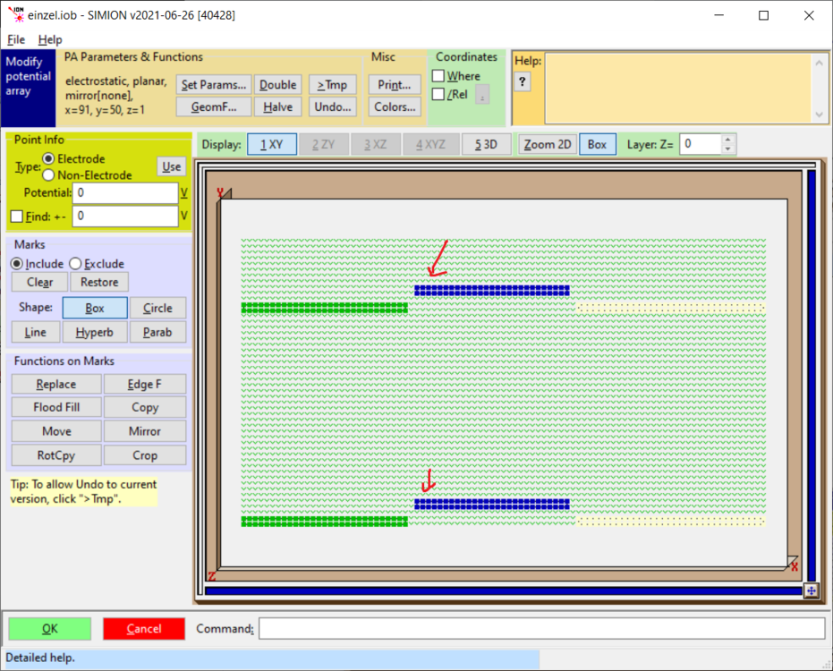
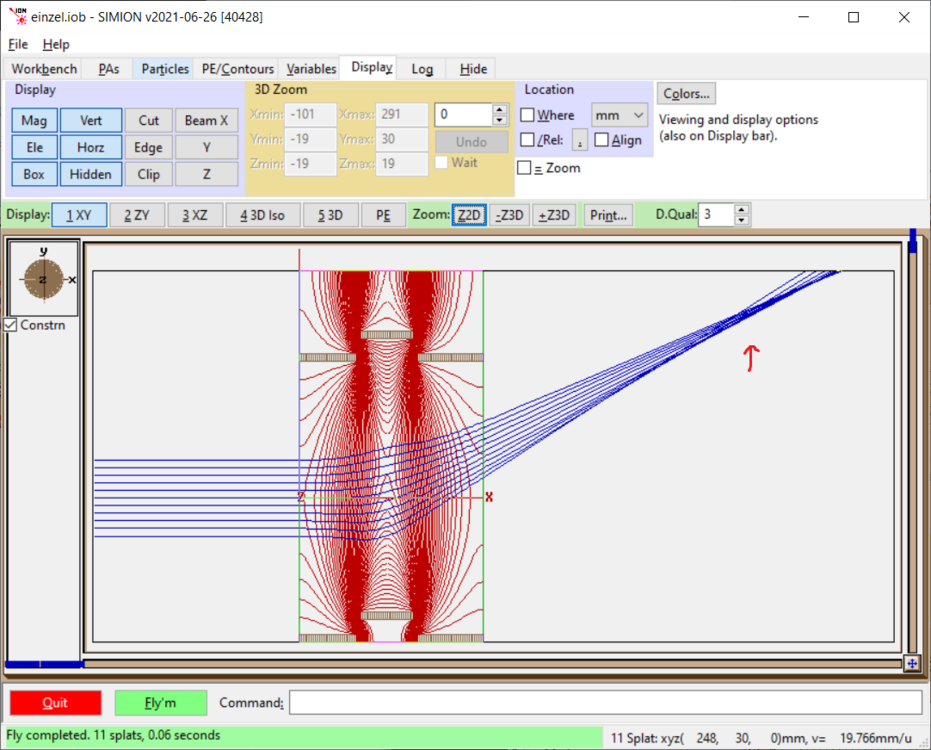
Certainly that affected things:
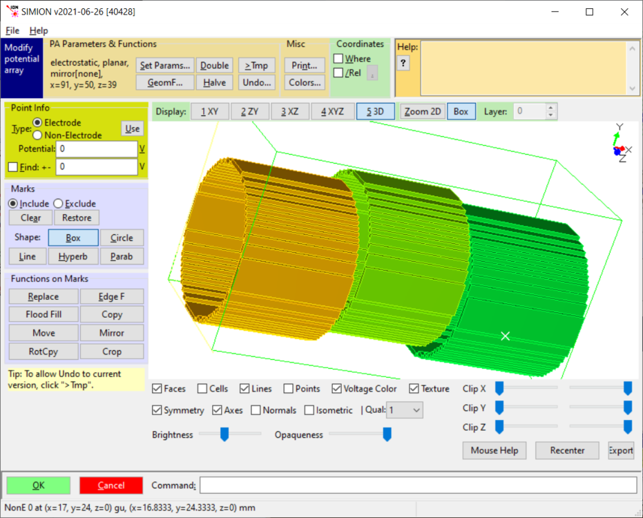
Now, for completeness, to prove this approach is meaningful, let’s model this as a full 3D planar (no mirroring) PA with the same 3 gu Y shift in the center electrode:
Here’s the result:
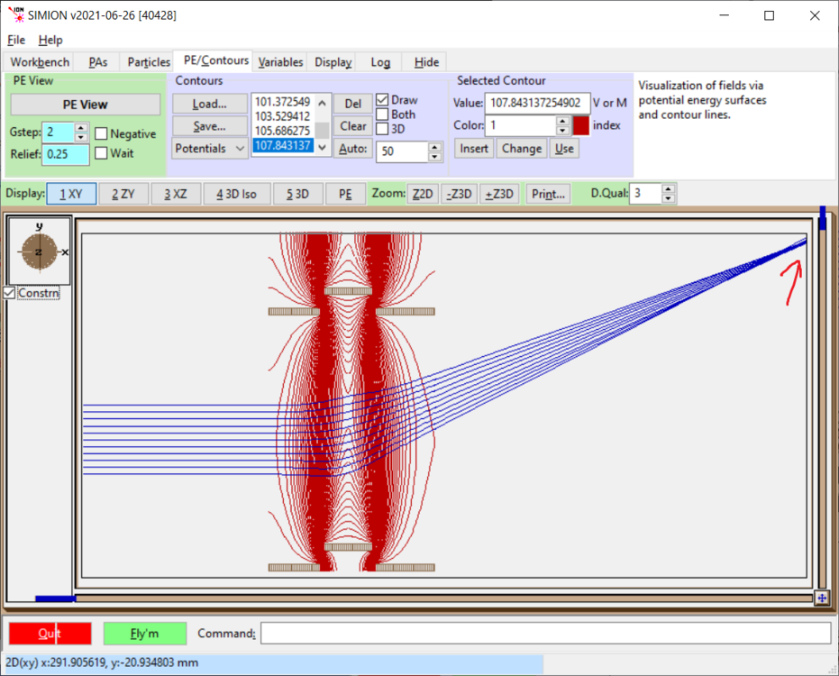
The deflection in the focus point is similar in magnitude in both the 2D planar and full 3D models. The 2D calculation perhaps is sufficient to answer the intended question.
In these examples a 3 gu shift was used to make the effect of the misalignment easier to see. It is possible to simulate misalignments less than 1 grid unit using Electrode Surface Enhancement / Fractional Grid Units, as done in SIMION Example: surface_enhancement (tilted_plates.iob).
See Also
Wannberg1985 B. Wannberg. Effects of mechanical imperfections in a hemispherical electron spectrometer Nuclear Instruments and Methods in Physics Research Section A: Accelerators, Spectrometers, Detectors and Associated Equipment. volume 239, issue 2, year 1985, pages 269-272 doi:10.1016/0168-9002(85)90725-9
Qinghao Wu, Yuan Tian, Ailin Li, Daniel E. Austin. doi:10.1016/j.ijms.2015.10.011 Simulations of electrode misalignment effects in two-plate linear ion traps. (Also preseted at ASMS 2015, Tue Poster 71. Simulations of alignment tolerance in two-plate linear ion traps Brigham Young University.) – Studied a linear ion trap consisting of two ceramic plates, with effect of plate alignment displacements in six degrees (pitch, yaw, roll, X, Y and Z) on resolution and transmission using SIMION.
[1] Machining division of SIS, specializing in precision, tight tolerances, and fine finishes for scientific instruments.
