Grid
Background
A grid is sheet of fine wires. Ideally, a grid provides an approximately equipotential surface (like a sheet of metal) yet allows particles to transparently pass through. In practice, the field between grid wires is not fully uniform but focuses and diverges particles to some extent, especially near the wires, and some fraction of the particles may hit the wires. Preferably, these undesirable effects are small though. The spacing between the wires is called the pitch. Grids with small pitches tend to reduce the field distortions at a cost of reduced ion transmission.
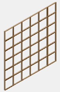
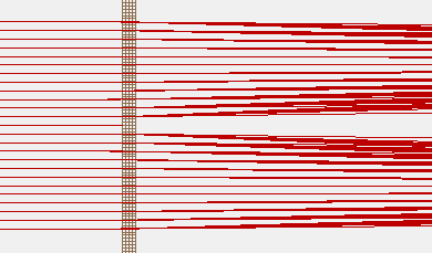
The figure above shows a small section of a square grid modeled to high resolution in SIMION (model taken from the Advanced ASMS Course). The effect on ions passing through is shown.
Grids have been used in TOFs, detectors, and elsewhere.
SIMION Methods
The following methods are available in SIMION for simulating grids:
Ideal grids (100% transmission) are easy to specify. Just create a PA file with a one-grid point thick sheet of electrode points. See near p. 5-3 to 5-5 in the SIMION 7.0-8.1 manuals.
Non-ideal grids (< 100% transmission) can be done in these ways:
You may be able to model the entire grid as a single large PA, provided the PA can accurately represent it. If there are too many holes, this might not be possible. See the GEM file in SIMION Example: nonideal_grid (8.1) or the one in the Advanced ASMS course (7.0). Also see RAM and Memory.
A more efficient method is to model a small section of the grid (e.g. a small number of wires) to high resolution in a 3D potential array. This small section of the grid can be effectively repeated via either placing multiple instances of the grid element into a workbench or using a user program (ion or PA jumping tricks). That requires Multiple PAs (or multiples instances of the same PA), so you’ll need to ensure that the fields match up between the PA instances. Luckily, a mesh typically has many Neumann Boundary Condition (e.g. along the wires or half-way between the wires), which you should make coincident with your PA boundaries (see Neumann Boundary Condition for more details). The original examples on this are in the “Non-ideal grids” sections of the Advanced ASMS Course or Application notes [http://www.sisweb.com/referenc/applnote/app-47.htm 47] and [http://www.sisweb.com/referenc/applnote/app-52.htm 52]. SIMION Example: nonideal_grid (8.1) (an older version of which is in the “Check For Updates” button in SIMION 8.0) provides both a “particle jumping” example (8.0) and a “potential arrary jumping” example (new 8.1 technique). SIMION Example: bradbury_nielsen_grid illustrates the case when there are RF voltages applied to the non-ideal grid wires.
Hybrid methods are also possible. Perhaps you can model a small section of the grid where the beam passes through as a non-ideal grid (to model beam scattering) and then the regions further away you can approximate as an ideal grid.
If you have a known equation for the theoretical transmission and deflection of the ions at the grid, you can incorporate this effect using a SIMION user program. A simple method may be to randomly kill 10% of the ions that pass the grid and/or apply a small random deflection angle. This may be sufficient if you already know how the grid behaves.
Links
Below are some links related to using grids in SIMION.
SIMION 7.0 Manual. p. 5-3 to 5-5 has some discussion on defining ideal grids in potential arrays. p. 9-7 has some discussion on simulating non-ideal grids via ion jumping tricks.
Non-ideal Grids sections of the Advanced ASMS Course. Uses ion jumping tricks. Files are included on the SIMION CD. See particularly grid2d*.gem and grid3d*.gem files.
SIS Application Notes on grids:
Examples: