Time Step Size
When SIMION computes the trajectory of a particle, it breaks the trajectory curve into many small steps. Each step in the trajectory is computed in sequence. The time duration the particle spends in each step is called the time step. Time steps (like all times in SIMION) have units of microseconds, and they can vary non-uniformly over the trajectory.
Importance of Time Step Size
Time step size has a significant effect on accuracy and performance. Smaller steps generally improve accuracy but take longer to compute because there are more steps.
Time step size is easy to change, often much quicker and easier to change than other factors affecting accuracy (e.g. PA grid unit size).
Visualizing Time Steps
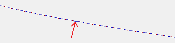
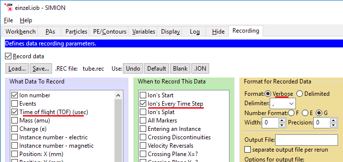
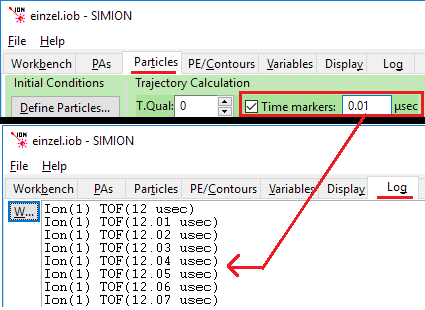
Time steps can be visualized. Upon Fly’m, a red dot will be drawn on the trajectory at every Data Recording event. So, enable Data Recording with the “Ion’s Every Time Step” event enabled. You may also wish to record the Time of Flight (TOF) or Position (X/Y/Z) values, for more quantitative display of time step sizes in the Log window/file:
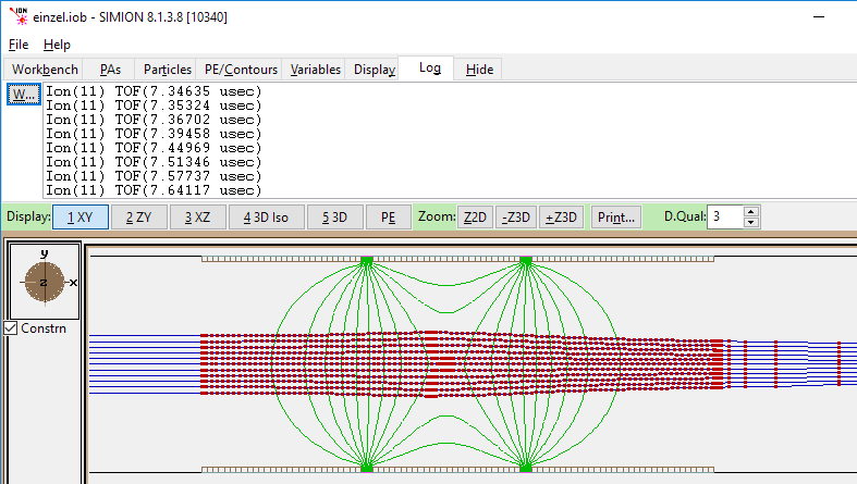
The red dots are then seen on the View screen, and times are printed in the log:
In the Einzel example shown above, the time steps normally corresponding to a movement of about one potential array grid unit (1 gu). In some more critical regions, warranting higher accuracy (entering/exiting PA’s, approaching electrodes, changing velocity, or high field curvature), the time step size is reduced. Time step sizes are even inceased in some non-critical regions, like outside of potential arrays where there are no fields.
Factors Affecting Time Step Size
There’s a number of factors affecting time step size, each of these is detailed later in this document:
The trajectory quality factor (T.Qual) on the Particles tab, which is the primary means to control trajectory quality.
Time Markers (if enabled) on the right side of the Particles tab can further reduce time-steps to a given multiple of microseconds.
tstep_adjust segment (if provided) in a workbench user program overrides the above defaults for even finer control.
Trajectory Quality Factor (T.Qual)
One of the easiest ways to change time step sizes is via the trajectory quality factor (T.Qual) on the View screen:
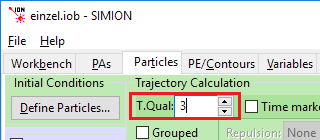
T.Qual values range from -500 to +500. The default of +3 is usually reasonable.
T.Qual values have this general meaning:
0 is the least accurate and defines time steps such that the particle travels about one PA grid unit per time step. Higher magnitude values (in both positive or negative directions) cause smaller time steps, which mean longer run times but higher accuracy.
Negative or zero values, cause time steps of 1/(1 + abs(tqual)) grid units.
Positive values (1..99), cause time steps to default to 1 grid unit. But this also dynamically reduces time-step sizes when applicable to improve accuracy, such as near special regions like high field curvature, velocity reversals or electrode surfaces. The CV limit (affecting how aggressively time steps are reduced within high field curvature regions) is set to 1/tqual.
Positive values (100..500), cause time steps to default to 1/(1 + abs(tqual - 100)) grid units, but otherwise this is the same as the previous case with regard to dynamically reducing time-step sizes with CV = 1/tqual.
T.Qual formulas are detailed in the Computational Methods Appendix of the SIMION User Manual (e.g. “H.23 How Trajectory Quality is Controlled” in 8.0/8.1).
Here’s some examples of T.Qual meaning:
A value of 0 indicates a step distance of 1 grid unit (gu).
A value of -9 indicates a step distance of 1/(1 + abs(-9)) = 0.1 gu.
A value of +9 indicates a step distance of 1 gu and dynamic step size reduction with CV = 1/9.
A value of 109 indicates a step distance of 1/(1 + abs(109-100)) = 0.1 gu and dynamic step size reduction with CV = 1/9.
Having particles moving approximately 1 grid unit per time step (e.g. T.Qual of 0 or 3) is typically reasonable. There’s no need to do super accurate trajectory calculations if your fields are not calculated that accurately, and there’s no need to do super accurate field calculations if your particle trajectories are not calculated that accurately. If particles were to traverse more than one grid unit per time step, then why did you waste time refining such a large array? If particles were to travese a small fraction of a grid unit per time step, then the imperfect interpolation of fields within a grid unit might not give much improvement, as the field is only as accurate as the PA grid unit. Typically the PA grid unit size (mm/gu) is more important for accuracy than T.Qual, as long as T.Qual is +3 or higher.
Sometimes large negative (e.g. -50) or large positive (e.g. +50)
T.Qual values are warranted if your fields are more accurate
than the grid unit size would suggest–e.g. uniform field between integrally
aligned electrodes or an analytically defined field via an efield_adjust
user program segment
(Electrode Surface Enhancement / Fractional Grid Units can also improve field accuracy).
0 or negative values are common especially in Grouped flying. For grouped flying (where all particles are flown simultaneously with the same time steps), this might warrant 0 (or negative values) to avoid the issue of one particle getting tiny time steps in a special region and slowing down the calculation of the rest of the pack, especially if accuracy is not highly critical. Some things like ion-gas collisional effects (Ion-Gas Collisions) introduce a fair amount of uncertainty already, so precise trajectories are not so critical, and moreover the rapid particle scattering makes the effects of positive T.Qual often irrelevant or counterproductive.
Time Markers
If you enable time markers (on the Particles tab), time-steps will be reduced to coincide with every multiple of the specified time in microseconds. This can be a quick way to force time-steps to be below a certain size in units of microseconds (rather than just grid units). It can also be useful to ensure data is recorded at exact time-intervals (e.g. as some have needed for computing an FFT/ICR work, Fast Fourier Transform (FFT)).
Accuracy and Time Step Size
The time-step size is important for accuracy but is also very easy to change, especially compared to the PA grid unit size. Smaller time steps don’t hurt, but they do increase the trajectory calculation time, although typically trajectory calculation time is very quick, so there is little harm experimenting with smaller time steps. If you reduce time-step sizes and observe no difference in trajectories meaningful to you, then this suggests that time step size is not a major source of error for your simulation and there is little need to do this. You may only need to fly one or a couple particles to make this determination.
You need to ensure, however, that time-step sizes are smaller than any special behavior you’d like to simulate on a smaller time scale:
RF fields (see Time-Dependent Field) should have time steps smaller than some fraction of the RF period in order for the particles to see the RF waveform accurately or at all. (See SIMION Example: octupole.)
Time dependent fields (Time-Dependent Field) with sharp voltage transitions may warrant finer control so that the time-step ends exactly on the voltage transitions. (See SIMION Example: buncher, SIMION Example: waveform, and “examplesfaims*wavelib.lua”.)
Time-steps near boundaries (other than built-in SIMION handling of electrode boundaries), such as a programatic Test Plane can require time-steps to end on that boundary if highest accuracy is desired. (See SIMION Example: test_plane.)
Collision models, particular those that model every ion-neutral interaction, like the hard sphere model (Collision Model HS1), can require the time-step size to be lower than some fraction of the mean-free-time between collisions to accurately model the collisions. (See SIMION Example: collision_hs1.)
Fields the happen to be much more accurate than the PA grid cell size might suggest (e.g. uniform fields between grid unit aligned electrodes or fields defined analytically with an efield_adjust segment), could benefit in a meaningful way from smaller time steps.
The more proper way to reduce these time steps for precise control
is often a tstep_adjust segment,
although increasing the T.Qual factor, or even using time markers,
can be simple and dirty fix avoiding any
programming, assuming particle trajectory calculation time is not an issue
in your simulation.
See Accuracy for many other things affecting accuracy.
tstep_adjust Segment in a User Program
If you need greater control over time-steps, you may define
ion_time_step explicitly in a tstep_adjust segment of a
user program.
The default time-step size can be overridden in a user program:
SIMION use various factors (including T.Qual as described above) to determine the recommended length of this time step. This is the
ion_time_stepreserved variable.If you have a
tstep_adjustsegment defined, SIMION will then call that segment, with theion_time_stepvalue initially set to the value determined in the previous step, but this segment may overwrite the value ofion_time_step.However, if trajectory quality (T.Qual on the Particles tab) is positive (not zero or negative), then it might be reduced by other factors, such as when approaching electrode surfaces. The
other_actionssegment will see the final value ofion_time_step.
If you don’t want to bother with defining a tstep_adjust,
just make your T.Qual a significantly high value to achieve a similar effect.
Some examples that alter time-step sizes via tstep_adjust segments include
SIMION Example: buncher - Ends time-step at exactly switch time
SIMION Example: test_plane - Ends time-step exactly on test plane.
SIMION Example: quad – Keeps time-steps below a fraction of the RF period.
SIMION Example: collision_hs1 - Ensures time-steps are below the mean-free-path of collisions.
SIMION Example: waveform - Ensures time-steps end of waveform edges (like buncher).
For example (similar to the octupole example):
simion.workbench_program()
adjustable min_step = 0.1  -- microseconds
function segment.tstep_adjust()
   -- Keep time step size <= min_step usec.
   ion_time_step = min(ion_time_step, min_step)
end