GEM Geometry File
A SIMION geometry file (GEM) defines electrode geometries using constructive solid geometry (CSG) primitives. CSG operations define shapes using unions and intersections of other basic shapes (e.g. a rectangular slab with a cylinder hole cut through it), a bit similar in concept to machining. GEM files are text files and have the file name extension of “.GEM”. SIMION can convert a GEM file to a PA file.
The GEM Syntax Reference (from the manual) is perhaps the first place to start. See also SIMION Example: geometry for examples. “courses\advanced” also has some notes on GEM files. Additional tips are given on this page.
Learning
Where to start learning about GEM files?
The Geometry Files appendix of the SIMION User Manual has an intro and reference on GEM files. It is included on this page too (SIMION 8.1 GEM Syntax Reference).
The SIMION Example: geometry example contains many GEM file examples.
SIMION 3D ASMS Course Notes though older has an intro and slides on GEM files.
SIMION 8.1 GEM Syntax Reference
Introduction
SIMION provides a variety of methods for defining the geometry of electrode/pole points in a potential array: The Modify function, Modify function geometry files (GEM), STL 3D CAD files, STL files or externally/programmatically defined potential arrays such as via the SL Libraries. SL Libraries Modify allows the user to interactively create, modify, and view electrode/pole point geometry. Geometry files are typically used for complex 3D geometry and/or an any geometry definitions that may need to be scaled (e.g. doubled without introducing the jags) or parameterized.
Geometry files can either be used in conjunction with Modify or as a stand-alone method for geometry definition within New. The Modify function has a geometry file development system within it. Modify’s geometry file development system provides a quick way to write, test, and modify geometry files.
Caution: GEM files are an advanced SIMION feature. It requires that you learn a geometry definition language. However, the effort you spend learning to create geometry files will add powerful capabilities to your SIMION bag of tricks.
SIMION 7 Note: SIMION 8.0 and SIMION 7.0 GEM files are identical, though 8.0.x version may add certain extensions.<footnote>8.0.4 added Lua macro and variable substitution support. See the page “GEM Geometry File > Macro Support” in the supplementary electronic documentation (Help menu).
What Is a Geometry File?
A geometry file is an ASCII file with a .GEM
extension (e.g. TEST.GEM) that uses a 3D solid geometry modeling
language to define the desired electrode/pole array geometry via a
series of fill (and other) instructions. Geometry instructions are
similar in structure to C language functions. However, unlike C
language functions, geometry language instructions are nested
(somewhat like in PASCAL) to enhance their power.
Note
This page is abridged from the full SIMION "Supplemental Documentation" (Help file). The following additional sections can be found in the full version of this page accessible via the "Help > Supplemental Documentation" menu in SIMION 8.1.1 or above:How Does SIMION Process a
Two Examples of a SIMION
A Quick Demo of Geometry Files
Geometry Language Rules
Classes of Instructions
Instruction Nesting Rules
Geometry Instructions
New/Updated Commands in SIMION 8.2
pa_define
- pa_define()
pa_define can now accept named parameters:
pa_define{nx=nx,ny=ny,nz=nz, gx=gx,gy=gy,gz=gz, wx=wx,wy=wy,wz=wz,
          symmetry=symmetry,mirror=mirror, type=type, ng=ng,
          dx=dx,dy=dy,dz=dz, unit=unit, surface=surface, refinable=refinable,
          filename=filename, nz_use=nz_use}
           -- new syntax
Examples:
pa_define{11, 12, 3, 'planar x', dx=1,dy=2,dz=0.5, surface='auto'} -- new syntax
pa_define(11, 12, 3, planar, x, e,, 1, 2, 0.5,, auto) ; old syntax
Common examples:
-- 2D planar array
pa_define{11, 11}

-- 2D cylindrical array
pa_define{11, 11, 1, 'cylindrical'}

-- 2D cylindrical array with x mirroring
pa_define{11, 11, 1, 'cylindrical x'}

-- 3D array with yz mirroring
pa_define{11, 11, 11, 'planar yz'}

-- 3D magnetic array
pa_define{11, 11, 11, type='magnetic'}

-- 2D planar array with 0.5 mm per grid unit and fractional surface enhancement
pa_define{11, 11, dx=0.5, surface='fractional'}

-- 2D planar array of 5 mm * 5 mm region with 0.5 mm per grid unit.
-- Each dimension will have 5/0.5 + 1 = 11 grid points.
pa_define{5*mm, 5*mm, 1, dx=0.5}
Named parameters require using {...} not (...).
When using named parameters or when compatibility mode is disabled
(using Lua -- comments), string values must
be quoted (single or double quotation marks), like 'planar' and
surface='auto'.
When using the {...} syntax, there are a few differences:
values are checked more strictly:
symmetrymust be ‘planar’ (or ‘p’) or ‘cylindrical’ (or ‘c’). Other abbreviations or capitalization like ‘Plan’ are not allowed.mirrormust be ‘’ (none), ‘x’, ‘y’, ‘z’, ‘xy’, ‘xz’, ‘yz’, or ‘xyz’.typemust be ‘electric’ (or ‘e’) or ‘magnetic’ (or ‘m’).
default values differ:
symmetrydefaults to'planar'(not'cylindrical').mirrordefaults to ‘’none’` (not “y”). So,pa_define(11,11,1,p,n)can now be writtenpa_define{11,11,1}, andpa_define(11,11,1)can now be writtenpa_define{11,11,1,'c'}.surfacedefaults to'auto'.
When using the older (...) syntax, the following enhancements were also made:
symmetrynow defaults to planar when nz > 1, rather than raising an error, so you can now dopa_define(11,11,11), and mirroring will be none in that case.
Description of parameters added in 8.1/8.2:
gx,gy,gz- number of grid units. These are one less than the number of grid points. These are requivalent:pa_define{gx=10, gy=20, gz=0} ; new style pa_define(11,21,1,p,n) ; old styleAdded in 8.2.
wx,wy,wz- distance in mm. These are equivalent:pa_define{wx=5, wy=10, dx=0.1} ; new style pa_define{5*mm, 10*mm, dx=0.1} ; new style #2 pa_define(51,101,1, p,n,e,, 0.1) ; old styleIf the distance converted to grid units is a fractional amount, the distance is rounded up to the nearest grid unit.
As a convenience, you can pass mm lengths in the first three positional parameters if you multiply the numbers by the unit object
mmas shown above.Added in 8.2.
refinable-trueorfalse- whether PA is allowed to be refined (default true). This is useful for PAs that store some type of special field that should not be automatically refined in the usual manner (e.g. magnetic vector potential, space-charge, dielectric constants, permeability, gas flow, etc.). It is used extensively in SIMION Example: magnetic_potential and SIMION Example: dielectric (Magnetic Potential and Dielectrics).Added in 8.2.
refine_convergence- Refine convergence objective in volts when the array is refined. Added in 2024-09-20.dx,dy,dz- Grid cell sizes in mm in x, y, and z directions. If dx omitted, it defaults to 1. If dy omitted, it defaults to dx. If dz omitted, it detaults to dy. Added in 8.1.unit-'gu'ornil(default) If'gu', then coordinates in the GEM file are in grid units rather than mm. Normally, coordinates are in mm. However, ifdx, dy, dzare all 1, then mm and gu are the same. Added in 8.1.surface-'none'(default - old SIMION 7.0/8.0),'auto'(automatic) or'fractional'(automatic with surface enhancement). See surface=auto option in pa_define [8.1.1.25]. Added in 8.1.filename- string ofnil(default). File name to assign generated PA. Otherwise the name defaults to the base file name of the GEM file but with a.paextension. This is especially useful with a GEM containing multiplepa_definestatements. Added in 2024-09-1w0.nz_use- number > 2 ornil(defaults to 2) - This applies to 2D planar arrays only. The array is projected in the +/- Z directions when placed on the workbench.nz_useis in grid points, and the actual width is one less thannz_usein grid units, in each direction +/- Z. To specify in mm units use*mmafter the number likenz_use=5.5*mm. This value is not saved in the PA file but only persists in memory and is used when the PA is placed into a workbench. Added in 2024-09-w0.
Compatibility: Changes added in 8.2EA-20170324.
include
- include()
include(filename)
When compatibility mode is disabled (using Lua -- comments),
the file name string must be quoted, like include("example.gem").
You can now pass additional parameters via the include() statement,
which are accessible via the expression ... in the included GEM file:
; 1.gem
pa_define(11,11,1, p)
include("2.gem", 5,6)

; 2.gem
local a, b = ...
box(a, b, a+5, b+5)
You can now also use global variables defined in a GEM file in an included GEM file:
; 1.gem
pa_define(11,11,1, p)
x = 5
e(1) { include("2.gem") }

; 2.gem
circle(x,x, 5)
Note: for this to work you must do x = 5 not local x = 5
(the latter defined a local variable only within the scope of the current file).
You can also define variables (as well as functions in the included GEM and for use in the main GEM file:
; myshapes.gem
function xplane(x0)
  return shape(function(x,y,z) return x == x0 end)
end
function myobject(r)
e(2) { circle(5,5, r) }
end

; 1.gem
pa_define(16,11,1, p)
include("myshapes.gem")
e(1) { xplane(15) }
myobject(5)
Compatibility: Added in 8.2EA-20170324.
shape
- shape()
shape(f)
Defines a custom GEM shape from a Lua function.
The given function must return another function that given the
coordinates (x,y,z) returns true or false whether
that points is inside the shape.
Example:
-- defining a paraboloid
pa_define{21,21,21, 'planar', 'xy'}
e(1) {
  shape(function(x,y,z) return (x/5)^2 + (y/5)^2 < z end)
}
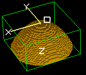
It’s convenient to wrap these in a named function for reuse:
local function paraboloid(x0,y0,z0, a, b)
  shape(function(x,y,z) return ((x-x0)/a)^2 + ((y-y0)/b)^2 > (z-z0) end)
end
e(1) { paraboloid(0,0,0, 1, 1) }
Other examples:
pa_define(101,101,1, p, surface=fractional)

local function yplane(y0)
  shape(function(x,y,z) return y==y0 end)
end
local function rbox(x0,y0, r)
  shape(function(x,y,z)
    return (x-x0)^4 + (y-y0)^4 <= r^3
  end)
end

e(1) {
  yplane(50)
}
e(0) {
  rbox(50,50, 40)
  notin { circle(50,50, 10) }
}
Compatibility: Added in 8.2EA-20170324.
intersect
- intersect()
intersect { ... }
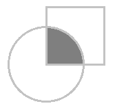
This is now a synonym of within but provided for improved readability.
intersect (or within) defines a volume that is inside the all the
listed shapes (i.e. their “intersected” or boolean “and” volume).
Example:
e(1) {
  intersect {
    circle(0,0, 10)
    polyline(0,0, 20,0, 20,5)
  }
  notin { circle(0,0, 5) }
}
Compatibility: Added in 8.2EA-20170324.
revolve_xy
- revolve_xy()
revolve_xy) { ... }
revolve_xy(angle) { ... }
revolve_xy(angle, angle2) { ... }
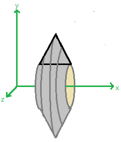
Forms a volume of revolution with the given angle (defaults to 360 degrees)
of the XY plane around the X-axis (CCW facing down positive X axis).
This is similar to rotate_fill but can be used in shape context.
The contents inside the brackets can be within’s and notin’s.
Example:
pa_define(21,21,21, p, surface=fractional)
e(1) {
  fill {
    within { revolve_xy() { within { box(0,1, 7,8) } } }
    notin { points(5,5) }
}}
The above is the same as this:
pa_define(21,21,21, p, surface=fractional)
e(1) {
  rotate_fill(360) { within { box(0,1, 7,8) } }
}
n(0) {
  fill { within { points(5,5) } }
}
Furthermore, within can be omitted (see omit fill/within commands),
so these two are equivalent (standard and simpler syntax):
revolve_xy() { within { box(0,1, 7,8) } }
revolve_xy() { box(0,1, 7,8) }
The revolve_xy can be more natural and powerful than rotate_fill.
The two parameter version of this function (added in 2024-08-28) will rotate between the two given angles, which can be expressed in the range +/- 720 degrees. The rotation is CCW from the more negative angle to the more positive angle. The order of the two angles is not important.
revolve_xy(-90, 90) { bbox(0,1, 7.8) }
Compatibility: Added in 8.2EA-20170324.
revolve_yz
- revolve_yz()
revolve_yz() { ... }
revolve_yz(angle) { ... }
revolve_yz(angle, angle2) { ... }
This is similar to revolve_xy but revolves the YZ plane figure around the
Y axis (CCW facing down positive Y axis).
It is equivalent to rotate_y(90) { rotate_z(90) { revolve_xy(angle) { ... } } }.
Compatibility: Added in 8.2EA-20170324.
revolve_zx
- revolve_zx()
revolve_zx() { ... }
revolve_zx(angle) { ... }
revolve_zx(angle, angle2) { ... }
This is similar to revolve_xy but revolves the ZX plane figure around the
Z axis (CCW facing down positive Z axis).
It is equivalent to rotate_z(-90) { rotate_y(-90) { revolve_xy(angle) { ... } } }.
Compatibility: Added in 8.2EA-20170324.
extrude_xy
- extrude_xy()
extrude_xy(z1, z2) { ... }
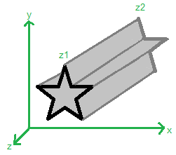
Extrudes the figure drawn in the XY plane in the Z direction from Z=z1 to Z=z2.
Example:
e(1) {
  extrude_xy(2, 8) {
    polyline(1,1, 10,19, 19,1)
    notin { circle(10,8, 2) }
  }
}
The above is equivalent to:
e(1) {
  within { polyline(1,1, 10,19, 19,1) box3d(-100,-100,2, 100,100,8) }
  notin  { circle(10,8, 2) }
}
The extrude_xy can provide a cleaner approach and can also be intersected
with other shapes like within { extrude() { ... } sphere(...) }.
If both z1 and z2 are omitted, then the extrusion is infinite in the
+-Z directions.
If only one is omitted, then the omitted one is assumed to be 0.
The order of z1 and z2 (swapped) doesn’t matter.
Example:
e(1) {
  extrude_xy() {  ; infinite extrusion in Z
    polyline(1,1, 10,19, 19,1)
    notin { circle(10,8, 2) }
  }
}
Note that e(1) { fill { within { extrude_xy(z2,z2) { fill { within { box() } } } } } }
can be written more simply as e(1) { extrude_xy(z2,z2) { box() } }.
Compatibility: Added in 8.2EA-20170324.
extrude_yz
- extrude_yz()
extrude_yz(x1, x2) { ... }
This is similar to extrude_xy but extrudes a YZ plane figure in the X direction.
It is equivalent to rotate_y(90) { rotate_z(90) { extrude_xy(x1, x2) { ... } } }.
Compatibility: Added in 8.2EA-20170324.
extrude_zx
- extrude_zx()
extrude_zx(y1, y2) { ... }
This is similar to extrude_xy but extrudes a ZX plane figure in the Y direction.
It is equivalent to rotate_z(-90) { rotate_y(-90) { extrude_xy(y1, y2) { ... } } }.
Compatibility: Added in 8.2EA-20170324.
scale
- scale()
scale(sx) { ... }

scale(sx, sy, sz) { ... }
Scales in the x, y, and z directions by the given factors. If sy or sz is omitted it defaults to sx.
This is identical to:
locate(0,0,0, sx, 0,0,0, sx,sy,sz) { ... }
Compatibility: Added in 8.2EA-20170324.
rotate_x
- rotate_x()
rotate_x(anglex) { ... }
Rotate counter-clockwise looking down positive x-axis.
This is identical to locate(,,,,,, anglex) (rot rotation).
Compatibility: Added in 8.2EA-20170324.
rotate_y
- rotate_y()
rotate_y(angley) { ... }
Rotate counter-clockwise looking down positive y-axis.
This is identical to locate(,,,, angley) (azimuth rotation).
Compatibility: Added in 8.2EA-20170324.
rotate_z
- rotate_z()
rotate_z(anglez) { ... }
Rotate counter-clockwise looking down positive z-axis.
This is identical to locate(,,,,, anglez) (elevation rotation).
Compatibility: Added in 8.2EA-20170324.
cylinder3d
- cylinder3d()
cylinder3d(x1,y1,z1, x2,y2,z2, r) { ... }
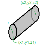
Defines a cylinder volume of radius r whose circular bases have centers (x1,y1,z1) and (x2,y2,z2).
This is identical to locate(x1,y1,z1,1,?,0,?) { cylinder(0,0,?, r,r,?) }
for appropriate values of ? but is more convenient.
Compatibility: Added in 8.2EA-20170324.
half_space
- half_space()
half_space(x1,y1,z1, ux,uy,uz)

half_space(axis, val)
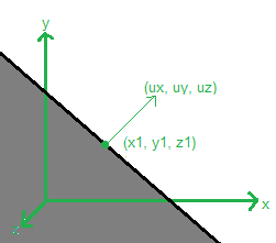
Defines the volume below the given plane. The plane is defined by the point (x1,y1,z1) and surface normal vector (ux,uy,uz) on that plane. The fill is in the direction opposite the normal vector. The normal vector length is not important (need not be normalized).
For example, the region x <= 2 is defined by half_space(2,0,0, 1,0,0).
The region x + y <= 4 is defined by half_space(2,2,0, 1,1,0).
There is also a short syntax:
half_space('+x')     -- same as half_space( 0,0,0,  1,0,0)
half_space('-x')     -- same as half_space( 0,0,0, -1,0,0)
half_space('+y')     -- same as half_space( 0,0,0,  0,1,0)
half_space('-y')     -- same as half_space( 0,0,0,  0,-1,0)
half_space('+z')     -- same as half_space( 0,0,0,  0,0,1)
half_space('-z')     -- same as half_space( 0,0,0,  0,0,-1)

half_space('+x', x)  -- same as half_space( x,0,0,  1,0,0)
half_space('-x', x)  -- same as half_space( x,0,0, -1,0,0)
half_space('+y', y)  -- same as half_space( 0,y,0,  0,1,0)
half_space('-y', y)  -- same as half_space( 0,y,0,  0,-1,0)
half_space('+z', z)  -- same as half_space( 0,0,z,  0,0,1)
half_space('-z', z)  -- same as half_space( 0,0,z,  0,0,-1)
This is useful for cutting another shape in half, like to define a half-sphere:
e(1) { intersect { sphere(10,10,10, 5) half_space('+x', 10) } }
Compatibility: Added in 8.2EA-20170324.
e, n
- e()
- n()
e(f) { ... }
n(f) { ... }
The electrode and non-electrode commands now accept a function as the parameter, which will be queried to determine the potential at the current point. This allows things like defining gradient voltages over electrode surface or analytical potentials in space.
Example:
; sphere with gradient voltage over surface
pa_define {21,21,21}
local function f(x,y,z)
  return x+y
end
e(f) { sphere(10,10,10, 10) }
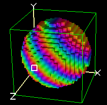
Only the coordinate transformations (locate) outside the e move the
potential function.
In the following case, the potential at grid points (x,y,z) inside the circle
will be f(x-1, y+2, z):
locate(1,-2,0) {
  e(f) {
    locate(0,2,0) {
      sphere(10,10,10, 10)
    }
  }
}
Normally PA’s don’t assign potentials of non-electrode points,
allowing Refine to assign their values, but you can use n to do this:
; generate theoretical field plus electrodes.
pa_define {21,21,1}
local function f(x,y,z)  return (x-10)^2 - (y-10)^2 end
local function g1(x,y,z) return f(x,y,z) >  5^2 end
local function g2(x,y,z) return f(x,y,z) < -5^2 end
n(f) { box(-inf,-inf, inf,inf) }  ; assign first (subsequent elecrodes overwrite)
e(f(15,10,0)) { shape(g1) }
e(f(10,15,0)) { shape(g2) }
Another example:
-- circular electrode with linear gradient potential
pa_define {30,30,1, symmetry='planar', mirror='xy'}
local function linear(x1,v1, x2,v2)
  return function(x,y,z)
    local f = (x - x1) / (x2 - x1)
    return (1 - f) * v1 + f * v2
  end
end
e(linear(5,100, 10,200)) {
  circle(0,0, 20)
}
- stl()
stl
stl(filename)
stl(filename, x, y, z)
Imports an STL file. The STL object can be used like any other shape, including cutting away other GEM objects from it.
If an optional (x,y,z) coordinate (in STL units) is passed, only the fully connected surface closest to that point will be imported. This is one mechanism to assign different parts of an STL different voltages, as an alternative to splitting up the system into multiple STL files. The test of connectivity assumes adjacent triangles touch on at least one vertex.
Example:
pa_define{30*mm,20*mm,20*mm, 'planar', dx=0.5, surface='fractional'}
locate(0,10,10) {
  e(1) {
    stl("two_cylinder-1.stl")
  }
  e(function(x,y,z) return -x/25 end) {
    stl("two_cylinder-2.stl")
    notin { cylinder3d(25,0,inf, 25,0,-inf, 3) }
  }
}
Example:
pa_define{100*mm,20*mm,20*mm, 'planar', dx=1, surface='fractional'}
locate(0,10,10) {
  e(1) {
    stl("two_cylinder.stl", 5, 15, 0)
  }
  e(2) {
    stl("two_cylinder.stl", 25, 15, 0)
  }
}
This is implemented in 8.2.0.10. The x,y,z parameters were added in 8.2.0.11.
inf
- inf
inf
This constant represents infinity. Previously a large number like 1e6 was used.
Example:
box(-inf,0, inf, 2)
Compatibility: Added in 8.2EA-20170324.
Note
This page is abridged from the full SIMION "Supplemental Documentation" (Help file). The following additional sections can be found in the full version of this page accessible via the "Help > Supplemental Documentation" menu in SIMION 8.1.1 or above:Developing, Testing, and Using Geometry Files
Accessing Geometry Files Via the
Accessing the Modify Geometry Development Tools
Extensions in 8.2
SIMION 8.2 makes major enhancements to the GEM syntax. Here is a summary of the new features described in more detail below.
Summary
New commands to define shapes easier or with fewer rotations:
cylinder3d()- easily defines a cylinder between two endpoints:cylinder3d(5,5,0, 5,5,10, 3). Use this rather thancylindersince it can be simpler and avoids locate rotations.half_space()- defines a volume below an infinite plane defined by a point and normal vector.half_space(5,0,0, 1,1,1). Use this rather than thanbox3dsince it is simpler and avoids rotations.shape()- defines your own custom shapes from analytical equations or function. Example:e(1) { shape(function(x,y,z) return x^2 + y^2 > z end). Complex surfaces can be defined directly in the GEM file. No need for doing this outside of a GEM file with thesimion.pas pa:fill()API.
New transformations:
extrude_xy(),extrude_yz()andextrude_zx()- extrudes a 2D image drawn in the given plane. For example,polylinenormally takes an XY plane drawing, which can then be wrapped in a rotation (locate) to another plane, but the rotation can be tricky. These commands make it more clear:extrude_yz() { polyline(0,0, 5,10, 10,0) } ; y,z points. Even XY extrusions can be specified more simply; for example to extrude from z=3 to z=5:extrude_xy(3,5) { polyline(0,0, 5,10, 10,0) } ; x,y points.revolve_xy(),revolve_yz(),revolve_zx()- define volumes of rotation in any given plane. These are suggested instead ofrotate_fill, which only operates in the XY plane without subsequent rotation. This command also defines a shape, so it can be used wherever shapes can be used, such as intersections, which is not possible withrotate_fill(except via the workaround of cutting away from arotate_fillusing a subsequentn(0) { }but that may cut more than the current shape).rotate_x(),rotate_y(),rotate_z()- rotates contained objects. They rotate counter-clockwise (CCW) looking down the positive end of the given axis. These are recommended overlocatecommands for clarity. Many times you can omitrotate_x|y|zas well when the commands above are used.
Other command improvements:
pa_define()accepts named parameters.pa_define {101, 101, dx=0.1}is equivalent topa_define(101,101,1, p, n, e,, 0.1,,,, auto). This is recommended. Please note that the{}syntax has different defaults than(), such as planar non-mirror symmetry and the newersurface='auto'. Another example:pa_define {101, 101, 1, 'planar xy', surface='fractional'}.pa_define()can accept mm array sizes rather than grid point sizes. The above example can be rewritten aspa_define {10*mm, 10*mm, dx=0.1}. It defines a 10 * 10 mm^2 region. This recommended.New
filename,nz_use, andrefine_convergenceparameters (added 2024-09-20).Support for multiple
pa_definestatements for creating a workbench of multiple PA’s from a single GEM (added 2024-09-20).
e(): andn()can accept a function parameter for defining gradient voltages over electrodes or analytic potentials in space.fillandwithincan be omitted when not necessary, for shorter GEM code. Usee(1) { circle(0,0, 50) }rather thane(1) { fill { within { circle(0,0, 50) } } }. See omit fill/within commands.intersect()is a synonym forwithin. The nameintersectmakes the meaning more clear and is recommended.e(1) { intersect { box(0,0, 10,10) circle(0,0, 10) } }.include()supports improved ways to pass variables to/from included GEM files (see examples below).infto represent infinity rather than a large number (e.g. 1e6).box(-inf,0, inf, 2). This is more clear and recommended.
Simpler syntax:
$(...)and#can be omitted around Lua code. They are no longer necessary:local w = 2 e(1) { for i=1,3 do box(i*10,0, i*10+w, 10) end }Using a Lua style comment
--in the file will disable compatibility mode supporting older deprecated GEM syntax such as space-delimited argument lists,+before numbers, and unquoted strings. New syntax.See New syntax for details on other language changes.
STL support
stl- include STL files in GEM file.stl("lens.gem"). Added in 8.2.0.10.
Be sure to also utilize SIMION 8.1 features like
surface='auto'orsurface='fractional'. See surface=auto option in pa_define [8.1.1.25].
New syntax
The GEM language has been significantly extended to merge GEM syntax, Lua syntax,
and prepreprocessing syntax (# $()).
Example:
-- new syntax
pa_define{wx=10, wy=10, wz=10, dx=0.5, surface='fractional'}
local function paraboloid(x0,y0,z0, a, b)
  shape(function(x,y,z) return ((x-x0)/a)^2 + ((y-y0)/b)^2 < (z-z0) end)
end
e(1) {
  for i=1, 3 do
    local y = i*2
    box(i*2, 0, i*2+1, y)
  end
}
e(2) { paraboloid(5,5,5, 1, 1) }
Previously, something like that would require various preprocessing code:
; old SIMION 8.1 compatible GEM
# local function round(x) return math.floor(x+0.5) end
# local wx, wy, wz = 10, 10, 10
# local dx = 0.5
# local nx = round(wx/dx) + 1
# local ny = round(wy/dx) + 1
# local ny = round(wz/dx) + 1
pa_define($(nx), $(ny), $(nx), p, n, e,, 0.5, surface=fractional)
# function paraboloid(x0,y0,z0, a)
  locate($(x0),$(y0),$(z0), 1, -90) {
    rotate_fill() {
      locate(,,, 1, 0,-90) {
        within { parabola(0, 0, $(a^2/4)) }
      }
    }
  }
# end
e(1) {
  # for i=1, 3 do
    # local y = i*2
    fill { within { box($(i*2), 0, $(i*2+1), $(y)) } }
  # end
}
e(2) { $(paraboloid(5,5,5, 1)) }
A more prominent change seen above is that variables and code used in GEM
commands need not be escaped anymore with # and $(...), as
as these are built into the language now.
Most Lua syntax is now available in GEM, including
Lua style comments: single line
--and multiline--[[...]]:-- this is line comment. --[[ This is a multi-line comment. ]] e(1) { box() } -- another line commentThese are similar to
;style comments, and the two comments styles must not be mixed in the same file.Added in 8.1.3.1 also.
Named parameters can be used with
{style function calls. This is primary used for thepa_define()command:pa_define {wx=10, wy=10, dx=0.1, surface='fractional'}Arbitrary Lua code, outside of commands braces:
local x = 1 for i=1,10 do x = x + i end print('hello world', x) e(1) { box(x,x, x+1, x+1) }if,forandlocalstatements within command brackets:e(1) { box() for i=1,4 do local j = i*2 box() if i % 2 == 0 then box() end box() circle() end polyline( for i=1,3 do i, i*2 end ) }This is convenient for geometric constructions. It is an extension to Lua syntax (normally statements cannot exist inside expressions such as inside braces, but this syntax extension allows it).
In normal Lua syntax, an
ifstatement likeif <a> then <b> endis only allowed inside a Lua statement list and the<b>can only be a Lua statement list. Normal Lua syntax does not allowifstatements inside “expression lists” like table definitions, e.g.x = {5,6, if z then 7, 8 end}is invalid in normal Lua, but GEM syntax extends Lua syntax to allows that and in this case the<b>is an expression list like its context. Intended usage is like this:s = true pa_define { 100*mm, 100*mm, if s then surface='fractional' end } polyline { for i=1,200 do 50 + 50*math.cos(i/100*math.pi), 50 + 50*math.sin(i/100*2*math.pi) end }Note that
surface='fractional'is not an assignment statement to a local variable but a named parameter to thepa_defineparameter list{...}.Note: Commas may be placed around statements but also can be omitted:
{local i=1, -i, if i > 0 then 3, 4 end, 5} ; these are equivalent
{local i=1  -i  if i > 0 then 3, 4 end  5}
{-1, 3, 4, 5}
It is recommended to omit commas around statements in most cases.
localcan be confusing in a few cases without commas, such aslocal i=1 - i(space before i is interpreted as a subtraction).No maximum line length. Prior to 8.1.3.1, more than 200 characters in a line were ignored.
The following GEM syntax is retained for compatibility:
Adjacent commas are interpreted as a
nilvalue, consistent with traditional GEM syntax. These are equivalent:box(,, 10, 10) box(,, 10, 10,) box(nil, nil, 10, 10) box{,, 10, 10} box{,, 10, 10,} box{nil, nil, 10, 10}Note that
,before an end brace does not pass anothernilvalue.Commas may be omitted between end braces
}}or end parenthesis)and an identifier, consistent with traditional GEM syntax. Example:e(1) { circle(0,0, 20) notin { box(0,0, 10,10) } circle(30,30, 10) }rather than:
e(1) {
  circle(0,0, 20),
  notin { box(0,0, 10,10) },
  circle(30,30, 10)
}
Omitting commas is recommended.
Using a Lua style style comment
--in the file will disable “compatibility mode.” With compatibility mode enabled, the following traditional GEM syntax is supported:;is interpreted as GEM line comment. (In regular mode,;is interpreted as a Lua statement or Lua table field separator):; first example t = {1, 2, 3} v = {4, 5} ; do this t = {1; 2; 3}; v = {4, 5}; ; can't do this -- second example, this line disables compatibility mode t = {1, 2, 3} v = {4, 5} -- do this t = {1; 2; 3}; v = {4, 5}; -- ok do to thisNumbers may be preceeded by an optional
+, consistent with traditional GEM syntax:box(-10, -10, 10, 10) ; these are the same box(-10, -10, +10, +10)
The
+is not recommended.Commas may be omitted between numbers in function arguments lists and table field lists, consistent with traditional GEM syntax:
circle(0 +20  -20)      ; these are the same
circle(0, 20, -20)
circle{0 +20  -20}
circle{0, 20, -20}
However, use of commas is strongly recommended to avoid ambiguity. Compare:
circle(0  -5  +20)    ; means circle(0, -5, 20)
circle(0 - 5+  20)    ; means circle(15)
circle(0, (-5 +20))   ; means circle(0, 15)
circle(0  f (5))      ; means circle(0, f(5))
pa_defineandincludecommands can accept unquoted strings, consistent with traditional GEM syntax, though only in compatibility mode. These are equivalent:include(example.gem) ; ok in compatibility mode include("example.gem") ; ok in compatibility mode; required in non-compatibility mode pa_define(11, 11, 1, planar) pa_define(11, 11, 1, "planar") pa_define(11, 11, 1, n, p, surface=fractional) pa_define{11, 11, 1, surface='fractional'} pa_define(101,101,101,"planar","xyz", "electrostatic",, 0.05,,,"gu", "fractional") ; new pa_define(101,101,101,planar,xyz, electrostatic,, 0.05,,,gu,fractional) ; old styleQuotes are recommended. Quotes are required when using the new
{...}syntax:pa_define{101,101,101,"planar","xyz", "electrostatic",, 0.05,,,"gu", "fractional"}
Note:
The preprocessing syntax
$(...)is still supported for compatibility. But some semantics of preprocessing have changed because it is now part of the language rather than as a separate preprocessing step that operatings on strings. If the old$(...)syntax is used, it is now more strict and may break some existing code in obscure cases.This used to be valid but is no longer valid because the
ifand{are not properly nested:#if x then locate(10) { #end box(0,0,10,10) #if x then } #endDo this instead:
function f()
  box(0,0,10,10)
end
if x then
  locate(10) { f() }
else
  f()
end
Keep in mind
$(...)can now only be used in the context of a command or parameter, and$(x)is usually equivalent toxexcept whenxis a string, where it is interpreted as GEM code to be compiled. So$("box(0,0,10,10)")is equivalent tobox(0,0,10,10). One obscure behavior:local function f() return "" end local function g() return "2,3" end box3d($(f()), $(g()), $(g()))
will be interpreted as
box3d(2, 3, 2, 3).
omit fill/within commands
The fill and within statements can now be omitted, to give simpler
syntax.
Also intersect is now a synonym for within but more clearly indicates its purpose.
The following examples are equivalent (original followed by simpler syntax):
e(1) { circle(0,0, 10) }  ; new
e(1) { fill { within { circle(0,0, 10) } } }  ; old

e(1) { box(0,0, 10,10) notin { box(2,2, 8, 8) } }  ; new
e(1) { fill { within { box(0,0, 10,10) } notin { box(2,2, 8, 8) } } }  ; old

e(1) { intersect { box(0,0, 10,10) circle(0,0, 10) } }  ; new
e(1) { fill { within { box(0,0, 10,10) circle(0,0, 10) } } } ; old

e(1) { box(0,0, 10,10) circle(0,0, 10) }  ; new
e(1) { fill { within { box(0,0, 10,10) } within { circle(0,0, 10) } } } ; old

e(1) { box(0,0, 10,10) notin{box(1,1, 9, 9)} box(3,3, 7,7) notin{box(4,4, 6,6)} } ; new
e(1) { fill { within { box(0,0, 10,10) } notin { box(1,1, 9,9) } }
       fill { within { box(3,3, 7,7)   } notin { box(3,3, 7,7) } } }  ; old
However:
within/intersectis still required if you need to take the intersection (AND) of two shapes rather than union (OR), as shown above.Inside a
fillthe order ofnotin’s andwithin’s is not important, but multiplefill’s are applied in order, and iffillis omitted, then eachwithinthat follows anotincreates a new fill. Therefore, order can be important whenfillis omitted. This is seen in the example above:e(1) { box(0,0, 10,10) notin{box(1,1, 9, 9)} box(3,3, 7,7) notin{box(4,4, 6,6)} }- thenotin’s only cuts from the immediately priorwithin’(s), not the following ones, nor ones before previousnotin’s.
Compatibility: Added in 8.2EA-20170324.
Workbench GEM files (*.wgem)
As of SIMION 2024-09-20 (with a 2022 license or above),
you can attach a GEM file to the entire workbench
by giving it the name of the IOB file but with extension .wgem.
This workbench GEM file can contain multiple pa_define statements,
one per PA instance, positioned within the volume (using locate),
and these not only construct and refine the PA’s but position them within the
workbench as PA instances, thereby fully constructing the field.
The following example is provided in examples\geometry\tube_multipa.wgem:
locate(0,-10,-10) {
  pa_define {20*mm, 20*mm, 20*mm, nz_use=10*mm, dx=0.1, filename="entrance.pa0", refine_convergence=1e-5}
}
locate(20) {
  pa_define {100*mm, 20*mm, 0*mm, 'cylindrical', filename="tube.pa", refine_convergence=1e-5}
}

e(0) {
  box3d(0,-10,-10, 20,10,10)
  notin { box3d(1,-9,-9, inf,9,9) }
}

e(1) {
  cylinder3d(15,0,0, 100,0,0, 5)
  notin {cylinder3d(-inf,0,0, inf,0,0, 4) }
}
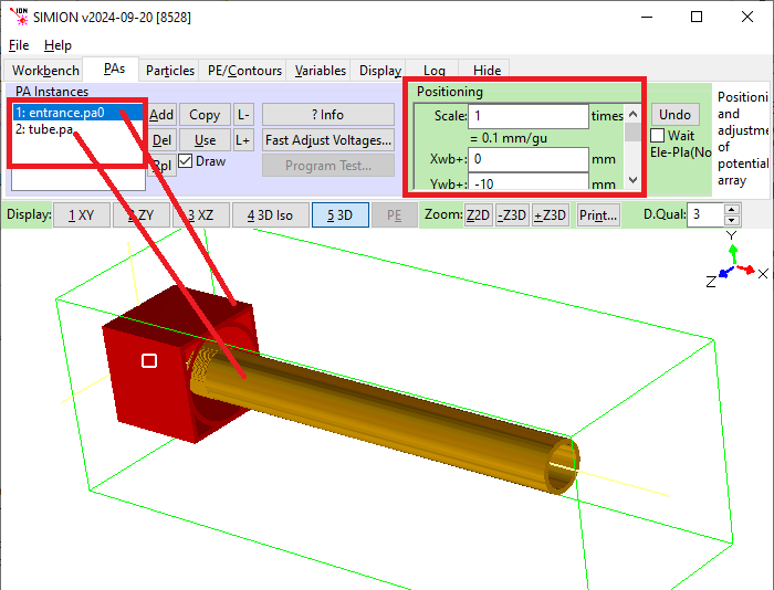
Fig. 20 IOB constructed from tube_multipa.wgem.
The idea of a workench GEM is to define and position both electrodes and
arrays with a space.
The electrodes define the electric field (boundary conditions), and the arrays
along with their locations wihin the workbench define how the volume is meshed
(divided up) for calculation.
You use locate() statements to position both these electrodes (e()’s) and
the arrays (pa_define()’s).
Wherever arrays and electrodes overlap, the electrodes there are imaged into the arrays.
There is more than one way to mesh a volume, and workbench GEM’s are intended to
provide more ease of tweaking this mesh from within the GEM file.
E.g. the location of the boundary between arrays can be defined with a variable
that can be easilly varied from a user program, or you can rebuild the system as
a single array.
The examples\quad\quad_wgem example now shows this:
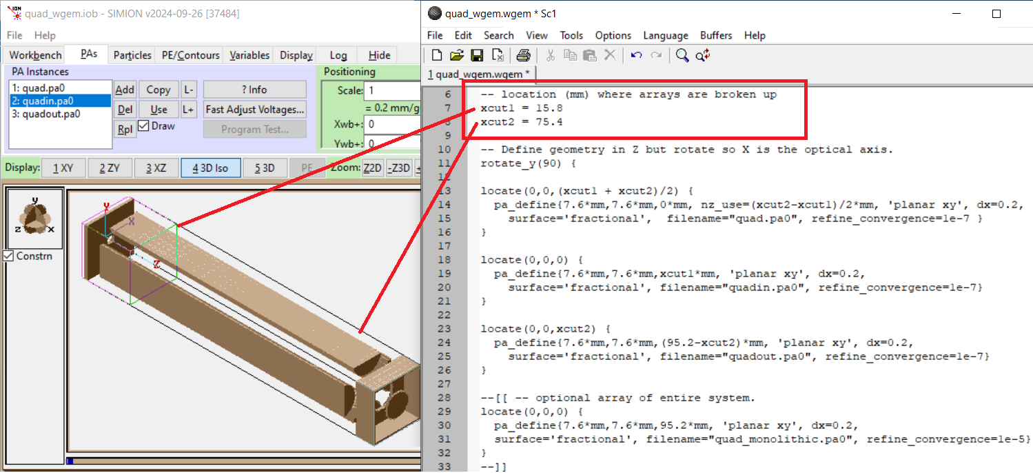
Fig. 21 examples\quad\quad_wgem example
Workbench GEM’s mainly benefit systems with multiple arrays, and there is little difference with systems with a single array.
Moreover, how the arrays are refined can also be encoded in the GEM.
We see this with the new refine_convergence parameter added to pa_define,
but it could be generalized, like in SIMION Example: field_emission uing nested arrays.
There are two ways to convert a .wgem to PA’s:
If you load the .wgem file from the main SIMION screen (New or Modify buttons or right click on Browse panel on the main SIMION screen), then all PA’s will be constructed but not refined. On entering the View screen, a new IOB will be created with the PA’s positioned appropriately as instances in the workbench. This positioning is lost, however, if you unload the PA’s without first saving the IOB.
When an .iob file is loaded, if not all its references potential arrays exist on disk, any associated .wgem file will be processed, the PA instances will be reconstructed from the .wgem file (ignoring PA instance definitions in the .iob file), and the PA’s will be built and refined. To reconstruct the PA instances, delete the PA files and reload the .iob.
Some tips:
Position the
pa_definestatements insidelocatestatements, which position the arrays within the workbench space.The PA instances in the IOB are created in the order the
pa_definestatements are listed in the .wgem file.For 2D planar arrays, set the
nz_useparameter onpa_define. This is in units of grid points (grid units plus one), but is ideally set in mm units by appending*mmto the number.For each
pa_definestatement set a thefilenameparameter to name your array file and set it types (basic .pa or fast adjustable .pa0). Lacking this, arrays will be named with a number postfix.The
pa_definesupports arefine_convergenceobjective voltage for the Refine; otherwise the default Refine parameters are used.Each
pa_definecorresponds with a PA instance in the workbench. You may have multiple instances of the same PA if the PA is given the same file name. It is assumed all instances have the same geometry definitions in the GEM file – this is not checked.
Some benefit of workbench GEM files:
Workbench GEM files provide a convenient way to break a system into Multiple PAs and quickly change how the breaking it done, e.g. whether to use a single array or multiple arrays and where to break them or what resolution to use for each array. Multiple PAs can be trickier than using a single array because you must ensure the breaking is valid, but being able to quickly change the breaking allows you to quantify the effect of breaking on your simulation.
Workbench GEM files can set refine parameters like
refine_convergenceto use when loading an IOB that creates the PA files.Workbench GEM files provide one way to construct IOB PA instance definitions programmatically/textually, which is not otherwise accessible (apart from the
simion.wb.instancesAPI) since .iob files are binary.
Limitations/possible future extensions:
Presently the workbench size cannot be set from the .wgem file. The size will expand to contain the PA instances. You can, however, use the
simion.wb.boundsAPI.Possibly provide some Lua API to re-process a .wgem file from within a workbench user program (without unloading the .iob).
Extensions in 8.1
Macro Support (e.g. variable expansion and preprocessing) - 8.0.4
As of SIMION 8.0.4, the GEM processor incorporates a preprocessor that allows things like variable expansion and loops (Issue-I 296). which allows GEM files to be more maintainable and easily modified. (This new feature is not described in the 8.0.4 manual except in a footnote.)
A new example GEM file (examples\geometry\macro.gem) illustrates
the use of this new feature:
; Example SIMION GEM file using preprocessing to expand Lua variables
; and macros.
; Preprocessing is a new feature SIMION 8.0.4.
;
; Lines starting with '#' or text inside $() are interpreted as Lua
; code and evaluated.  If $() contains an expression (rather than a
; statement), the result is outputted.  All other text is outputted
; verbatim.

; These variables are intended to be adjusted by the user.
; Note: both # and $ syntax are shown for demonstration.
# local ro = 45     -- outer radius, gu
# local ri = 40     -- inner radius, gi
$(local nshells = 4) ; number of shells

; Now do some calculations on those variables.  Note: math.ceil(x) is
; the ceiling function: it returns the integer closest to but no
; greater than x.
# local hw = math.ceil(ro * 1.1) -- half width, gu
# local nx = hw * 2 + 1          -- num array points in x

; Define array size.
pa_define($(nx),$(nx),$(nx), planar, non-mirrored)

; Declare a function to be used later.
; This returns the voltage for electrode number n.
$( local function volts(n)
     return n^2 * 10 + n + 1
   end )

; This locate centers the shells in the array.
locate($(hw),$(hw),$(hw), 1, 0,0,0) {
; Now define a loop that creates each shell.
# for n=1,nshells do
#   local rop = ro * n / nshells
#   local rip = ri * n / nshells
    electrode($(volts(n))) {  ; example calling a function
      fill {
        within{sphere(0,0,0, $(rop))}
        notin {sphere(0,0,0, $(rip - 1))}
      }
    }
# end
}

; Note: the following two lines are equivalent:
fill { within { box3d(0,0,0, $(nx),0,$(nx)) }}
# _put("fill { within { box3d(0,0,0, " .. nx .. ",0," .. nx .. ") }}")

; Print output to the log window.  This can be
; useful for debugging.
# print("Hello from GEM file. nx=" .. nx)
The example examples\geometry\polygon_regular.gem illustrates
subroutines in GEM files, allowing you to in effect create your own
reusable shapes:
# -- builds regular polygon in XY plane
# -- with center (x0,y0), radius r, and n sides.
# function regular_polygon(x0,y0, r,n)
  polyline(
    # for i=1,n do
    #   local theta = math.rad(i/n*360)
        $(x0+r*math.cos(theta)), $(y0+r*math.sin(theta))
    # end
  )
# end

e(1) { fill {
  within { $(regular_polygon(50,50, 40,6)) }
  notin  { $(regular_polygon(50,50, 20,6)) }
} }
When SIMION loads a GEM file containing macros (e.g. macro.gem), it
processes those macros, writes the result to temporary file
(e.g. macro.processed.gem), and loads that temporary file.
It also possible to do your own GEM file preprocessing outside of SIMION with your own programming tools. This was more popular prior to the introduction of the above feature but can still be useful in some cases.
The
pa_definecommand has various extensions:pa_define(nx,ny,nz,symmetry,mirroring,type,ng,dx,dy,dz,gu,surface=fractional)pa_definewas extended to allow definition of grid cell sizes(dx, dy, dz)in anistropically scaled PAs. See Anisotropically scaled grid cell - GEM File Supportpa_defineallows a PA to be marked “not refinable” by using an underscope in thepa_definecommandtypeargument (e.g.electric_ormagnetic_). This is equivalent to settingsimion.pas pa.refinabletofalse. This is useful for PAs that store some type of special field that should not be automatically refined in the usual manner (e.g. magnetic vector potential, space-charge, dielectric constants, permeability, gas flow, etc.). It is used extensively in SIMION Example: magnetic_potential and SIMION Example: dielectric (Magnetic Potential and Dielectrics). Added in 8.1.1.0.pa_definesupports a newsurface=fractionalnamed parameter to enable surface enhancement, for higher accuracy. See Electrode Surface Enhancement / Fractional Grid Units. There is also a lesser versionsurface=autodescribed in Intersecting within and notin_inside and surface=auto option in pa_define [8.1.1.25].
Changes
2024-09-20 A Support workbench GEM file (
\*.wgem) associated with the workbench IOB file and which positions PA instances in the workbench and builds them. See Workbench GEM files (*.wgem).2024-09-20 A GEM files can contain multiple
pa_define’s to generate multiple PA’s (preliminary support).2024-09-20 A Add
pa_defineparameterfilenameto set the default PA filename to use.2024-09-20 A Add
pa_defineparameternz_useto set Z projection of 2D planar PA instance in workbench.2024-09-20 C Add
pa_defineparameterrefine_convergenceto set default refine convergence objective in volts.2024-09-20 C Example(quad/quad_wgem): Add sub-example using workbench GEM file.
a Example(geometry): Add
tube_multipa.wgem- tube with 2D and 3D regions, built from single workbench GEM.2024-09-20 X Fix 1/2 gu adjustment for
circle()inside arevolve*()orextrude*()inside a scale other than 1 (e.g. usinglocate,scale, orpa_definewithdxparameter).surface='fractional'is not affected, onlysurface='auto'(default) orsurface='none'which apply this offset. Acylinder3dthat is infinitely long (from +/-inf), which is implemented in terms ofcircleandextrude*(), is also affected.rotate_fillis not affected, onlyresolve. Example:pa_define{11,11,11, surface='none', dx=0.1} extrude_xy() { circle(0,0, 0.5) }2024-08-24: added two parameter form of
revolve_xy(),revolve_yz(), andrevolve_zx()to rotate between two angles.8.2EA-20170324: Major enhancements. See Extensions in 8.2.
8.1.3.1: Some changes consistent with 8.2EA-20170324.
8.1.2.4: Macro lines beginning with ‘#’ can now be indented with tabs and spaces. This allows cleaner indenting of GEM code.
8.1.1.25: A GEM: New
surface=autoparameter inpa_define. This provides a simple way to more accurately position curved surfaces and cutout (notin) volumes when not using surface enhancement (surface=fractional). This particularly applies tocircle/sphere/cylinder,hyperbola(Issue-I 371),parabola,polyline,notin, and others. Surface enhancement is still better, but if you don’t want to use surface enhancement for some reason, then this is better than nothing. See surface=auto option in pa_define [8.1.1.25].8.1.1.25: C GEM:
within_inside_or_on/notin_inside_or_onnow shift the electrode surface outward by a small 0.0001 gu offset. (within_insideandnotin_insidealready apply this offset but in the reverse redirection.) This more reliably ensures points “on” the shape boundary are filled even when small numerical round-off occurs in operations likepolylineand scaling. Example:fill{within_inside_or_on{box(1,1,5,5)}}andfill{within_inside_or_on{polyline(1,1, 5,1, 5,5, 1,5)}}behave identically now, as expected. [*]x GEM/polyline:
polylineGEM command accuracy has been improved. Previously, the points on the polygon edge might not be optimally filled with the desired electrode/non-electrode point type. This particularly affectedwithin_inside/notin_inside/within_inside_or_on/notin_inside_or_onrather thanwithin. However, undersurface=fractional, it also affectedwithin/notin(but is somewhat cosmetic since electrode point types on the surface are not critical for field accuracy undersurface=fractional). Example:polyline(10,5 15,5 15,10 20,10 20,15 15,15 15,20 10,20 10,15 5,15 5,10 10,10)(cross).8.1.1.25: C GEM/Surface: PA grid points that precisely align to an edge of a
within/notinfill volume are made to be electrode points ifsurface=fractionalorsurface=autois enabled. In other words, anotininside aneor awithininside ann(both of which remove electrode material) will be treated as an “inside” fill to avoid removing the electrode points from the border. This largely avoids fiddling withwithin_inside/within_inside_or_on/notin_inside/notin_inside_or_onfill variants sincewithinandnotinwill now just do the right thing. The default option (surface=none) retains the old behavior for compatibility though. Example:e(1){fill{within{box(1,1,5,5)} notin{box(1,1,5,5)}}}ande(1){fill{within{box(1,1,5,5)}}} n(0){fill{notin{box(1,1,5,5)}}}both create a 4x4 hollow box with infinitesimally thin walls undersurface=autoorsurface=fractional. See surface=auto option in pa_define [8.1.1.25].8.1.1.25: c GEM:
polyline,points, andpoints3dcommands can now accept an arbitrary number of points. Previously these were limited to 100, 100, and 65 points.8.1.1.25: x GEM: Fix
polylineproblems when using exactly 100 points. [*sf-t1338]
