Converting from 3D CAD (STL) Format to PA Format
This page describes how to convert a CAD model into a SIMION potential array (PA) file. The STL format is a triangulated surface mesh format supported by many CAD programs.
First obtain a CAD model that you wish to import into SIMION. In your CAD program, export the CAD model as STL format. For testing, you may use the two_cylinder.stl included in SIMION Example: geometry [8.1.0 zipped or 8.2.0.10 unzipped], which is a simple 2D cylindrical lens and can be useful to test the accuracy of the conversion (e.g. hole radius). You might wish to use one of the many STL files available on the Internet. We found many quality STL models at 3D CAD Browser (www.3dcadbrowser.com).
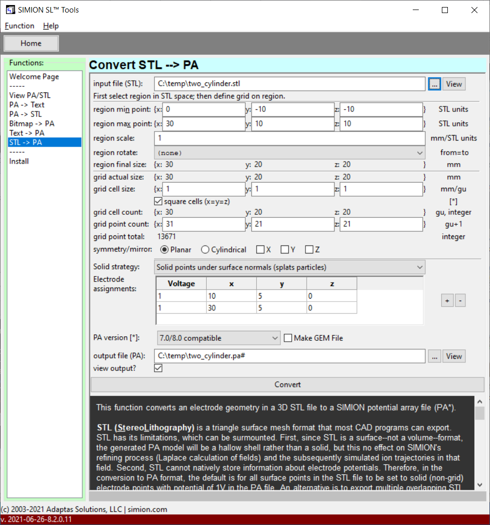
In SL Tools, select the “STL -> PA” function and select your STL file from the “…” button next to “input file (STL)”. The conversion page appears as follows (you may wish to expand the window size):
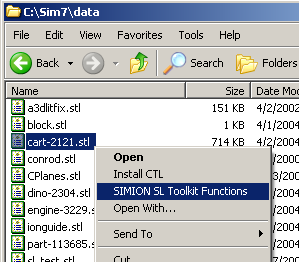
(If you had used the “Install” function in SL Tools to install file associations, you could have instead right clicked on the STL file in Windows explorer and selected SIMION SL Toolkit Functions, as shown below, to view or convert the file.)
Clicking Convert will perform the conversion. The bottom status bar should display “Converting…” followed by “Success.” If “view output?” was enabled, the output file will load (a progress bar displays) and the following Quick View window appears:
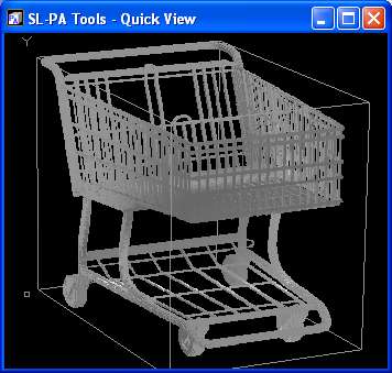
As before, you can rotate the model by dragging the mouse, or press ESC to quit. The PA file can now be loaded into SIMION. See the previous screenshots in the Introduction section showing the cart simulated in SIMION.
Note
This page is abridged from the full SIMION "Supplemental Documentation" (Help file). The following additional sections can be found in the full version of this page accessible via the "Help > Supplemental Documentation" menu in SIMION 8.1.1 or above:Conversion Options
Accuracy
Assigning Voltages to Electrodes
Multiple electrode systems. By default, all solid points will be set to 1V solid electrodes (or electrode #1 if using PA# files). This is because STL files do not store electrode voltages. If your model has multiple electrodes, there are at least two ways to to avoid that:
Use the electrode assignments option to specify voltages on fully connected STL surfaces nearest to the given points (x,y,z) in STL units. This requires SIMION 8.2.0.11 (20210619) or above.
You can use the Modify function in SIMION to adjust the voltage on certain regions of your generated PA or make further changes. In particular, the “Find” function comes in handy to change the potentials of all solid points in a region to some other value. This is what we did for the quadrupole example above. There is a screencast on Find/Replace that may be helpful, and Find/Replace is further described in Chapter 5 of the print manual. In 8.2 EA-20151103, there is also “Flood Fill” function that alternately can be used (available in Modify or alternately in Lua
pa:flood_fill).SL Tools supports loading multiple overlapping STL files, one per each electrode, directly into a single PA# file, so that Modify/Find becomes unnecessary. In your CAD software, simply export each electrode or component as an individual numbered STL file–e.g.
myfile-1.stl,myfile-2.stl, andmyfile-3.stl. Then in SL Tools, specify a template for the input file name using the “%” character as a placeholder (e.g. “myfile-%.stl”). SL Tools will search for and read all matching SL files and assign these voltages of 1V, 2V, and 3V respectively. This is shown in the figure below.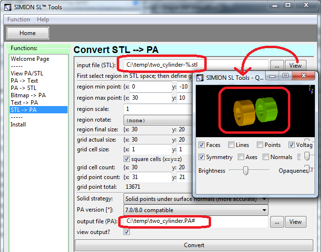
This relies on the assumption that the coordinate system in all the STL files is the same, as is usually in CAD softwares (if not, there may be still be some ways to force it, such as adding a common box around all components). The details are specific to your CAD software; for example,
In SolidWorks, when exporting the STL file, uncheck the box “Save all components in an assembly to a single file”, and this will save multiple STL files (e.g. tof-1.stl, tof-2.stl, and tof-3.stl), one per each component.
In Autodesk Inventor, use the “One File Per Part Instance” STL export option [1,2]. This option might not be available in older versions [3].
[1] Autodesk Inventor Help > Export Files > STL File Save As Options lists the various STL output options.
Using Mirror Planes and Symmetry
Consider the SIMION example examples\geometry\two_cylinder.stl, which is a 3D model of two cylinder lens.
The model has mirror planes and cylindrical (axial) symmetry, which can be utilized.
We explore here how to import this model as a 3D PA with mirror planes or a 2D PA with cylindrical symmetry.
If you just convert it with the default options, without any symmetry/mirroring, you get this 13671 point 3D array:
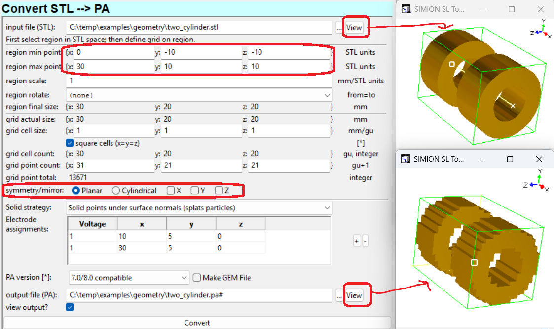
(In practical usage you will likely want to reduce the grid cell size to improve accuracy, which increases the number of points further, and assign electrode numbers, but we are using this just as a demonstration.)
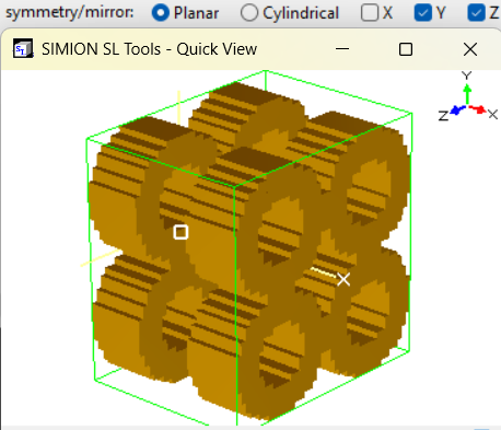
If you simply enable Y and Z mirroring, you will get this undesirable result:
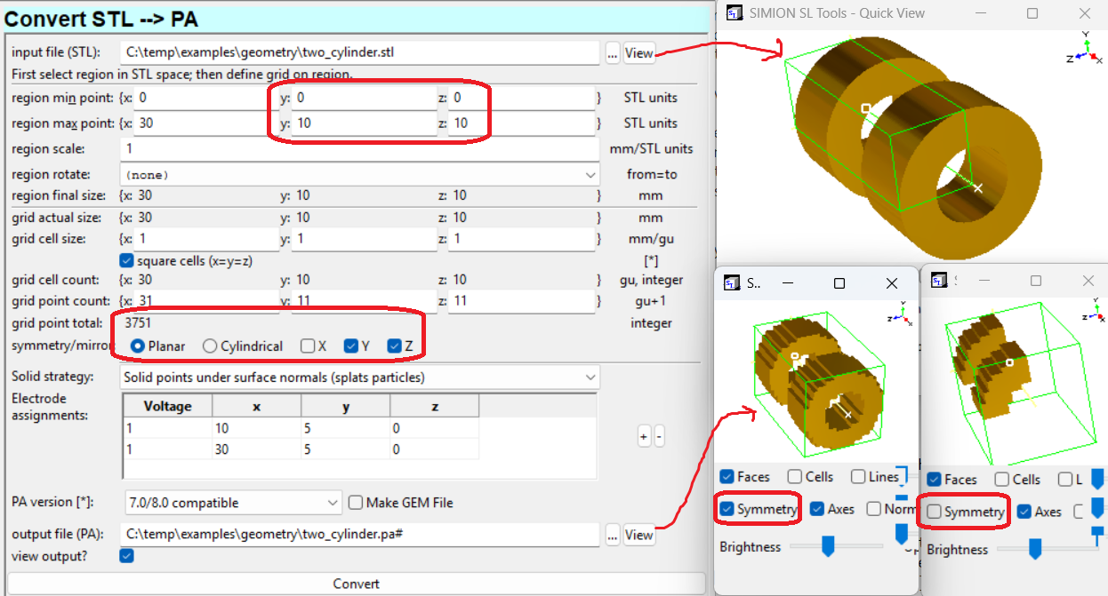
What you need to do is adjust the “region min/max points” to define a box around the region you
want to import into the array, i.e. the first (positive) quadrant.
So change the y and z regions from [-10, 10] to [0, 10], which results in this 3751 point array.
Notice on the View button on the input file (STL) displays a green box around the
selected region to import in the output file (STL) you can toggle display of the PA symmerty
projection on/off.
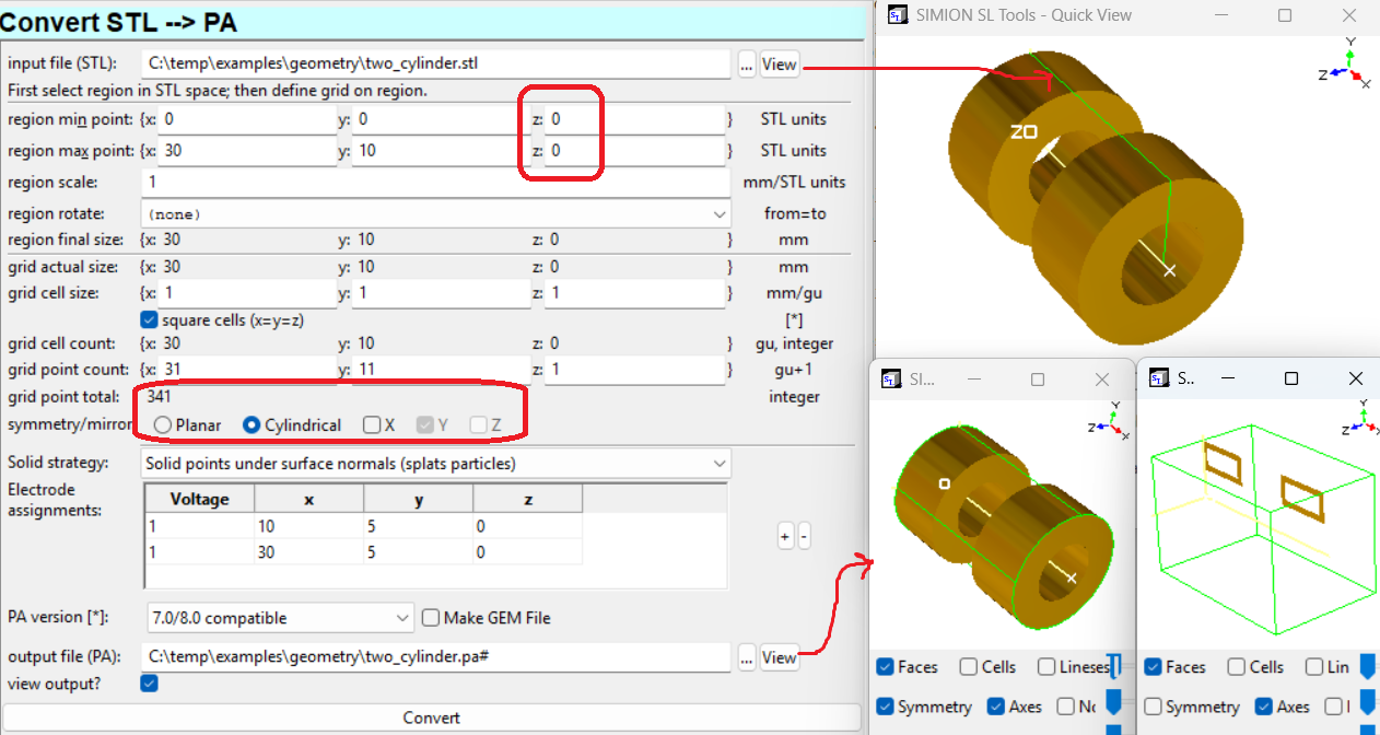
To rather create a 2D cylindrical PA, set the “region min/max point” on the two z’s both to the same value, through the axis of rotation, and ensure the y region is the upper-half as before. This defines the import region as a thin cross sectional slice through the axis, which symmetry will rotate around the axis. The resultant 2D PA has only 341 points.
Another possibility is to model the only the first quadrant of your system in your CAD software, which when exported will create an STL file that is 1/4 the size and will convert more quickly. However, the resultant PA, if using mirroring, will be the same size as before. The only reason to do this is if you want the STL-to-PA conversion to run faster.
For 2D cylindrical arrays, SIMION assumes the x axis is the axis of rotation.
If the axis of symmetry in your STL model is in another direction,
you will need to rotate the STL model, either in your CAD software or
using the region rotate parameter in SL Tools.
The region final size in z must be 0.
Mixing GEM and STL Files
Mixing STL with GEM and other SIMION drawing
After you import an STL file into a PA, you can draw additional objects into the PA using the other Geometry Input Methods. For example, load the PA into the SIMION Modify screen and use the “GeomF” button to “Insert” a GEM file into the existing PA (optionally positioning it).
STL files can also be used inside GEM files (as of 8.2.0.10). The “Make GEM File” option is a quick was to start this.
pa_define{30*mm, 20*mm,20*mm, 'planar', dx=1, dy=1, dz=1, surface='auto'}
locate(-0, 10, 10) {
e(1) { stl("two_cylinder.stl", 10, 5, 0) }
e(2) { stl("two_cylinder.stl", 30, 5, 0) }
}
There are features in the GEM file to assign different STL files or connected parts of an STL file different electrode numbers or locations:
pa_define{60*mm,20*mm,20*mm, 'planar', dx=1, surface='fractional'}
e(1) { locate(0,10,10)  { stl("two_cylinder-1.stl") } }
e(2) { locate(30,10,10) { stl("two_cylinder-2.stl") } }
This will apply a voltage gradient to an electrode:
e(function(x,y,z) return -x/10 end) {
  stl("two_cylinder-2.stl")
}
Note
This page is abridged from the full SIMION "Supplemental Documentation" (Help file). The following additional sections can be found in the full version of this page accessible via the "Help > Supplemental Documentation" menu in SIMION 8.1.1 or above:More CAD Package Specific Hints
Dielectric Material
Manipulating STL Files
Major Changes
8.2.0.10/11
New “solid fill” solid strategy, which fills all points between electrodes with solid electrode points. Supports surface enhancement too.
New “electrode assignments” option to assign voltages (V) to fully connected surfaces closest to the given point (x,y,z). Also available in
stl()command in GEM files.New “Make GEM file” option
New symmetry/mirroring switches. No longer needs done via Modify Set.
Fixes
View GUI sometimes does not display surface enhancement.
Reduce number display precision to 16 digits to avoid 0.10000000… numbers.
Display surface enhancement in 3D viewer (like SIMION).
Fix rotation support in “surface enhancement” solid strategy.
EA20150727
New “Flood Fill” button in Modify (and Lua API), to to replace points in contiguous region containing selected point (bucket fill).
EA20130509
Add “Export” button on Modify/View 3D views to export PA or IOB to STL file. Same as
simion.wb:save_stl().
8.1.1.1
New solid strategy: “solid under surface normals”
New option to overlap/compare STL and PA objects in “STL->PA” View output window available via “PA” and “STL” checkboxes, for checking conversion accuracy.
Fix non-“square cells” with “region rotate” defined. mm/gu sizes were being applied to wrong axes, causing obvious distortions to geometric aspect ratio.
8.1.0-TEST11
aniso-PA - Anisotropically scaled PAs now supported in viewing and STL/Text <-> PA functions.
8.0.7-TEST11
New “no extra solid points” solid strategy, for improved conversion accuracy.
Major reorganization of STL->PA screen and its command-line options. This is intended to be more clear and also support 8.1 extensions.
See SIMION Software Change Log for full changes.