SL Tools Tutorial
SL Tools Tutorial: Importing/Exporting PA Files–Describing the import of CAD models into SIMION, plus other potential array manipulation capabilities using the SL Tools utility.
Abstract
This article describes how to import 3D CAD models into SIMION as 3D PA files, import 2D bitmap images into SIMION as 2D PA files, and convert SIMION potential arrays to text format, all using the SL Tools (sltools.exe) program available with SIMION (8.1/8.0/SL).
Introduction
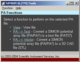
The SL Tools utility in SIMION 8.1/8.0 (and also in the older SIMION SL Toolkit 1.2) expands the functions that can be performed on PA files:
Import/export 3D CAD models to/from 3D SIMION potential array (PA) files.
Import/export scalar potential and vector field data of refined potential arrays from/to ASCII text files for use in third-party or custom programs.
Import/export 2D bitmap images to/from 2D SIMION potential array (PA) files.
Quickly view PA files from Windows Explorer (OpenGL).
Some examples of the CAD import feature are given below:
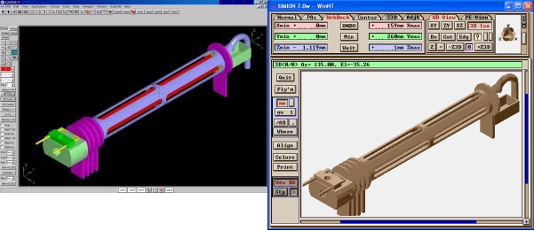
Figure: (left) CAD model of a quadrupole drawn in CAD software and exported to STL format. (right) STL file converted to a PA file (160 x 1120 x 260) using the new PA tools and then loaded into SIMION.
Shown above is a solids model drawn in a CAD program and exported as STL surface files. We then converted the STL file into a SIMION potential array file (PA or PA#) for use in SIMION. “What is an STL file?” you ask. The STL format is a triangulated surface mesh format exportable by most CAD programs. STL comes in two formats (binary and ASCII), both of which are supported by the SL Tools.
Here are more complex models imported into SIMION, not that it makes any sense to do these, but it gives an idea of the types of geometries that may be done–e.g. complex surfaces and intricate non-ideal grids.
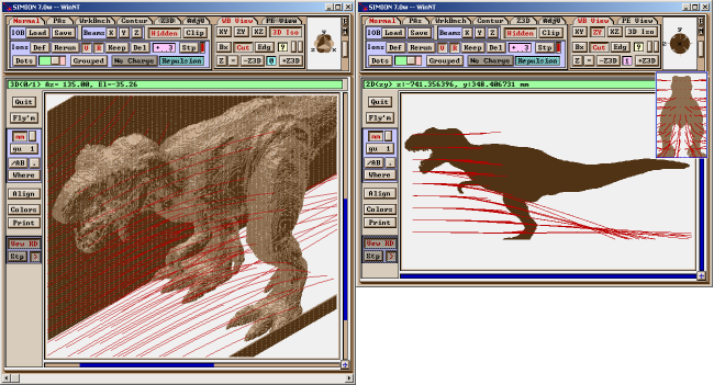
Figure: Dinosaur held at +24V between two grounded walls (front wall cut out for display). Positive ions fly toward dinosaur (190 x 350 x 750). STL Source: (c) 3D CAD Browser (www.3dcadbrowser.com) (2001), by Ross Blackburn). 24723 polygons, 22969 points.

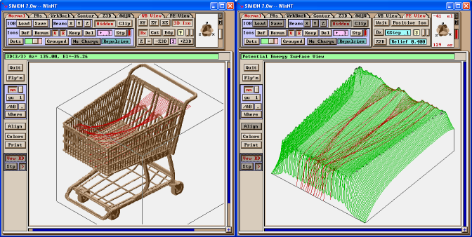
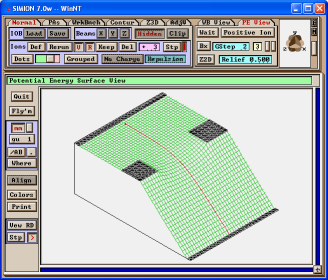
Figure: (top) original “shopping cart” STL model, (c) 3D CAD Browser (www.3dcadbrowser.com), by Wenet Locker (2001). 13314 polygons, 13907 points. (bottom left) Model acting as a non-ideal grid (300 x 350 x 300). The shopping cart is held at 120V. Not shown is an enclosing cube held at ground potential. (bottom right) potential energy view of XZ cross section.
Installation
System Requirements
This utility has the same System Requirements as SIMION. The OpenGL rendering can be intensive for large PAs, so a reasonably good graphics card is recommended if you wish to make use of the (optional) Quick View window.
Installation
SL Tools is installed by default by SIMION. It is accessible via the “SL Tools” button on the SIMION main screen.
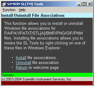
You may wish to use the “install file associations” function in the SL Tools software to allow SL Tools to be easily accessed from Windows Explorer by right clicking on data files. You may need to run SL Tools as administrator to make that change though (right click sltools.exe in Windows Explorer and select “Run as Administrator”). If can anytime use the “uninstall” link to remove associations.
Converting from 3D CAD (STL) Format to PA format
For converting CAD models (STL) to PA files, see Converting from 3D CAD (STL) Format to PA Format.
Converting from a 2D Bitmap (BMP/PNG/JPEG/PNM) to PA Format
It is also possible to convert a 2D bitmap image (e.g. BMP/PNG/JPEG/PNM file) into a 2D SIMION potential array (planar or cylindrical).
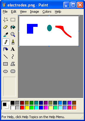
Below we created a simple 2D image of an electrode system in MS Paint. We drew each electrode in its own color so that the SL Tools will assign a different fast adjustable potential to each electrode (1, 2, 3, …).
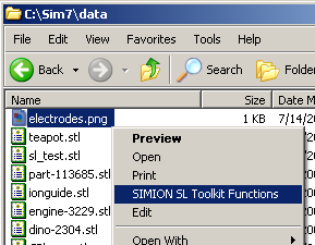
To convert this image, navigate to the image file in Windows Explorer, right click on the file, and choose “SIMION SL Toolkit Functions” as shown above and then select Raster –> PA.
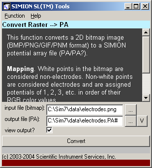
All the fields are filled in with defaults. The fields have similar meaning as described in the previous section. You can use the … buttons to browse for a file or the V button to quickly view a generated PA file. When view output? is selected, the generated PA file will display immediately after conversion.
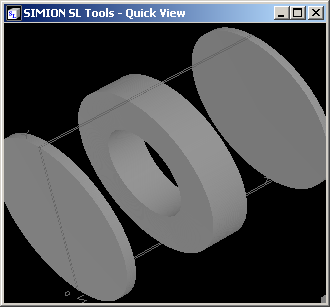
Press Convert to perform the conversion. The PA file is generated and the following quick view displays (before cylindrical revolution):
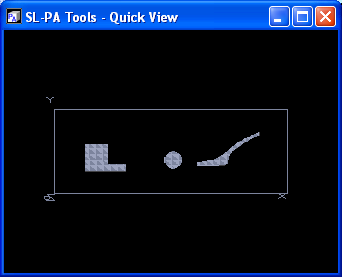
Press ESC to exit the quick view. You can now load the file into SIMION. Below is the result after changing the symmetry to cylindrical via the Modify function:
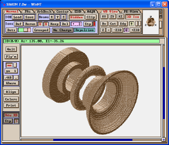
Note that this 3D model is a surface of revolution of your bitmap with respect to the x-axis.
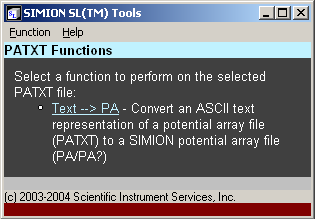
Converting a PA File to ASCII Text
The SL Tools can also convert SIMION PA files to ASCII text. For example, the SL Tools can generate a text file listing the solid points, potentials, or potential gradient vectors at each point (x, y, z) in the PA file. This text file then may be imported into other programs or used directly for special applications.
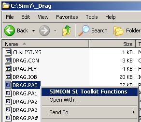
For this example, we will ASCII-tize the 2D
“DRAG.PA0” potential array (refined, fast adjusted, and saved)
that comes with SIMION:
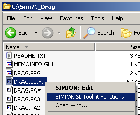
To convert a PA file, first locate the file in Windows Explorer, right click on the file, and select “SIMION SL Toolkit Functions” and select PA –> Text.
You can convert any type of PA file (PA, PA#, PA0, PA1, …). However, if we want to generate a text file containing potentials or potential gradient vectors, we must select use a refined and fast adjusted PA or PA0 file, else all the values at space points will be zero.
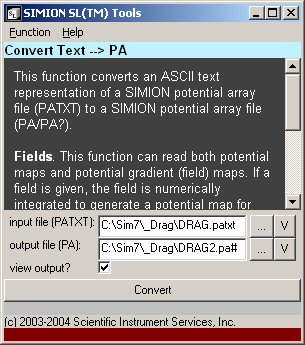
The following screen then displays allowing you to modify conversion parameters.
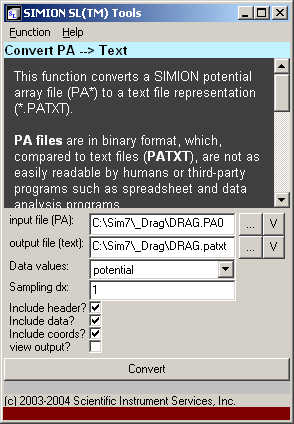
As before, the … button may be used to browse for an input or output file. The V button will display a preview of the selected PA or text file.
The Data values selection may be either “potential” to generate potential values or “field” to generate potential gradient vectors (fields). Sampling dx represents the sampling width in grid units. The default (1) will sample at every grid point. If this value is fractional, interpolation will be performed between grid points. The various include …? options can be unchecked if you want the output to be more terse. Check view output? if you want the generated text file to immediately display after conversion (if not, you can still use the V button on the output file to view the file). You might want to uncheck this if the file will be very large.
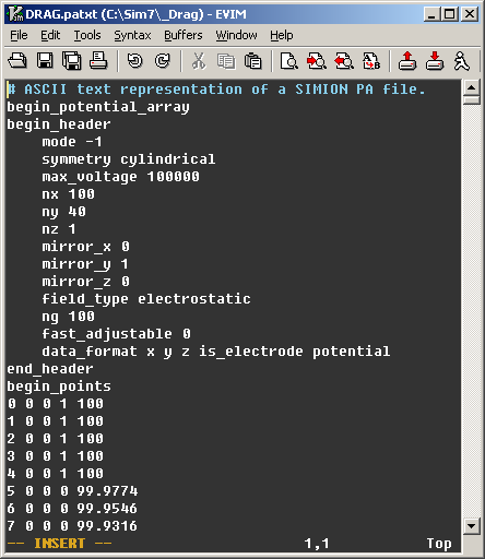
Below is the output.
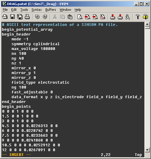
Here is the output if we instead set dx = 1.5 and data values to “fields.”
Converting from ASCII Text to a PA File
We can also go the reverse direction (ASCII to PA).
Giving the output:
Importing electric and magnetic field vectors: One particular application of the Text –> PA function is importing field vectors into PA files. You have two options here. First, you can convert each component of the field into a separate PA file, and then use techniques like in SIMION Example: field_array (solenoid_pa.iob) to represent a vector field in SIMION 8.1 based on those three PA’s. That is the most direct route and avoids additional numerical loss in precision. Second, you may be able to convert the field into a scalar potential and then represent it as a single PA. The latter is not generally possible for magnetic fields in regions where there are non-negligible currents (see Magnetic Potential).
SL Tools “Text -> PA” will take care of the converting the vector E-field into an electric potential or converting a vector H-field into magnetic scalar potential. This is done via a numeric line integration (simple trapezoidal integration, averaged over multiple paths, with single grid unit integration steps). Beware that if using a magnetic field, you should enter the H-field, not necessarily the B-field (which is related by B = (mu_r * mu_0) * H). The E-field should be in units of V per grid unit. The H-field should, like the B-field, be in units of gauss (i.e. H*mu_0).
SIMION Example: magnetic_potential (spotential_from_bfield.iob) demonstrates another way to convert vector fields to scalar potential PA’s via Lua, which can provide a bit more flexibility and also works on analytically defined fields.
Converting a PA File to STL
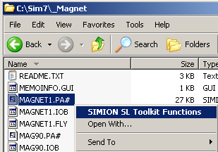
To convert a PA file to an STL file, right click on the PA file in Windows Explorer and select “SIMION SL Toolkit Functions” and then PA –> STL.
The parameters are as before. Click Convert.
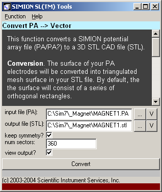
The keep symmetry option preserves and cylindrical symmetry or mirroring in the PA (otherwise, the STL model will be flat).
The num sectors option defines the number of circle sectors used in approximating the solid of revolution (applicable only to cylindrical symmetry PAs). The higher the valve, the better the quality.
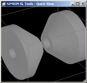
A preview of the generated STL file is displayed:
For converting an entire IOB file to an STL,
see simion.wb:save_stl() in SIMION.
The Quick Viewer
As shown in the previous sections, the SL Tools can display STL and PA files via the V buttons. You can also invoke the quick viewer by right clicking on a PA or STL file in Windows Explorer and selecting the SIMION SL Toolkit Functions and then selecting the View … function. This provides a fast way to see what is inside files.
Advanced: Command-line Usage
For advanced users, the SL Tools program can also be fully controlled from the command-line:
sltools - SL Tools for SIMION SL
(c) 2003-2022 Adaptas Solutions, LLC.
usage: sltools [command] [--help] [--nogui] args...

Top-level options:
  --help    - Displays this help message.
  --version - Displays SIMION version.
  --nogui   - Disable GUI (console mode only).
  --reserved-memory arg  - Number of bytes of memory to reserve for PAs.
Command may be one of
  stl2pa    - Convert STL to PA.
  bitmap2pa - Convert bitmap (BMP/PNG/PNM/GIF) to PA.
  pa2text   - Convert PA to text.
  text2pa   - Convert text to PA.
  view      - Quick view of STL or PA file.
  install   - register Windows file extensions.
  uninstall - unregister Windows file extensions.
For additional help on each function, add a --help option after the
function name (e.g. sltools stl2pa --help).
Conclusion
We’ve described how to use the new sltools.exe program to import 3D CAD and 2D raster files into SIMION. We also looked at exporting PA files to text or STL files, as well as the quick view features.